4 0
T O R K E L 8 2 0 / 8 4 0 / 8 6 0
P r o g r a m m a E l e c t r i c A B
Z P - B S 0 6 E R 1 0 1
14
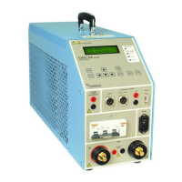
TXL Extra Loads
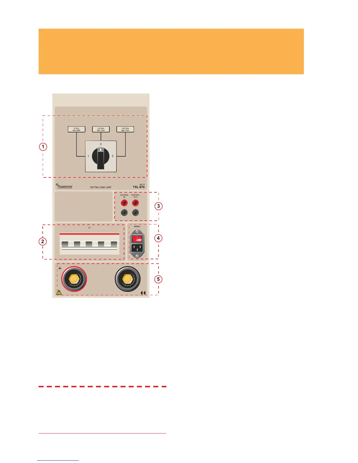
3 – Connection terminals
for the battery
+
(Terminal)
Positive (+) current connection for battery being
tested.
- (Terminal)
Negative (-) current connection for battery being
tested.
Insulation voltage to ground: 2200 V
4 – Control
CONTROL IN
Input for control signal from TORKEL-unit. Galvani-
cally isolated.
CONTROL OUT
Output used for the control signal sent from TORKEL
to the adjacent TXL-unit. Galvanically isolated.
5 – Mains
MAINS
Connector used for mains supply, equipped with
ON/OFF switch.
1 – Selector switch
Selector switch used to set the desired voltage range
and/or resistance value.
2 – Circuit breaker
F1
Voltage-controlled circuit breaker that connects the
resistors in the TXL Extra Load to the battery.
Note F1 will not latch or remain at upper (ON)
position unless the mains switch is turned
on and a control signal from TORKEL
is present at the “CONTROL IN” input.
Furthermore, TORKEL must be in the ”Test
battery” sub-menu.


 To Next Page