8 VIDAR ZP-BR01E BR0150GE
3 INSTRUMENT DESCRIPTION
3
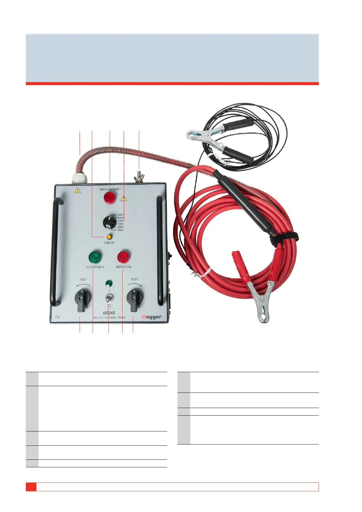
Instrument description
1. High voltage cable. For connection of the test voltage
and ground to the vacuum breaking chamber.
2. Yellow CANCEL indicator lamp. Lights up when:
▪ the test interval has exceeded one minute.
▪ you try to conduct a one minute test less than two
minutes after the latest test.
▪ the HIGH-VOLTAGE indicator malfunctions.
3. Red HIGH-VOLTAGE warning lamp. Shows that the
high voltage is applied.
4. Test voltage selector. Five standard voltages and one
customized voltage, determined at the factory.
5. Protective earth (ground) terminal.
6. SAFETY CONTROL KNOBS. Both knobs must be
turned simultaneously to their TEST positions to apply
high voltage to the object being tested.
7. Green ACCEPTABLE Indicator lamp. Lights up when
the breaking chamber test result is positive.
8. Power ON/OFF.
9. Red DEFECTIVE indicator lamp. Lights up when:
▪ the breaking chamber test result is negative
▪ the flashover threshold voltage is too low.
1 4 5
6976
32
8