EasyManua.ls Logo

MEIG SLM156 - Page 40

MEIG SLM156
64 pages
Print Icon
To Next Page IconTo Next Page
To Previous Page IconTo Previous Page
Loading...
MeiG_SLM156_Hardware Design Manual
MeiG Smart Technology Co., Ltd
39/63
Table 18 Pin description of PCM interface
Pin name
Pin number
I/O
Description
Note
PCM_CLK
26
IO
PCM clock
1.8V power domain
PCM_DOUT
24
DO
PCM data output
1.8V power domain
PCM_DIN
25
DI
PCM data input
1.8V power domain
PCM_SYNC
23
IO
PCM data
simultaneous signal
1.8V power domain
I2C_SCL
45
OD
I2C clock
External pull-up of 1.8V is
required
I2C_SDA
44
OD
I2C data
External pull-up of 1.8V is
required
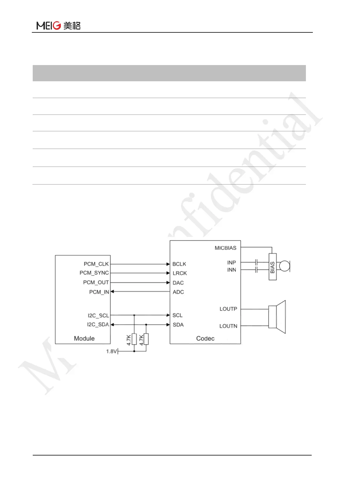
AT command can be used to set clock and mode, and the default setting is short frame mode,
PCM_SYNC=8kHz, PCM_CLK=2048kHz.
The following figure shows the reference circuit of PCM interface with external Codec chip:
Figure 18 Reference Circuit of PCM

Table of Contents