B1-2
DISASSEMBLY INSTRUCTIONS
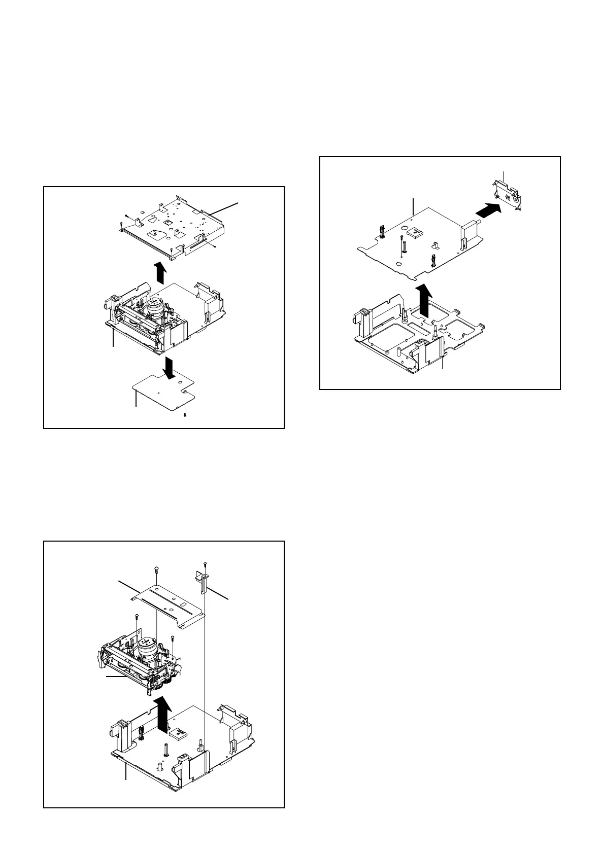
1-7: JACK PLATE AND SYSCON PCB (Refer to Fig. 1-7)
Remove the screw (1).
Remove the Syscon PCB in the direction of arrow (A).
Unlock the 2 supports (2).
Remove the Jack Plate in the direction of arrow (B).
Fig. 1-7
Jack Plate
(1)
Deck Holder
Syscon PCB
(A)
(2)
(2)
(B)
1.
2.
3.
4.
1-6: DECK CHASSIS (Refer to Fig. 1-6)
1.
2.
3.
4.
5.
Remove the screw (1).
Remove the Plate Cover Light.
Remove the 3 screws (2).
Disconnect the following connectors:
(CP605, CP1001, CP4001, CP4002 and CP4003).
Remove the Deck Chassis and Shield Cover Deck in
the direction of arrow.
Fig. 1-6
1.
2.
3.
4.
5.
6.
Remove the 2 screws (1).
Remove the screw (2).
Remove the screw (3).
Remove the Deck Shield Plate in the direction of arrow (A).
Remove the screw (4).
Remove the Bottom Shield in the direction of arrow (B).
Fig. 1-5
(1)
Deck Shield Plate
VCR Block
(2)
(1)
(A)
(B)
(4)
(3)
Plate Cover Light
Syscon PCB
(1)
(2)
(2)
Deck Chassis
(2)
1-5: JDECK SHIELD PLATE AND BOTTOM SHIELD
(Refer to Fig. 1-5)
Bottom Shield
Shield Cover Deck