34
English
Fig. 15
Fig. 14
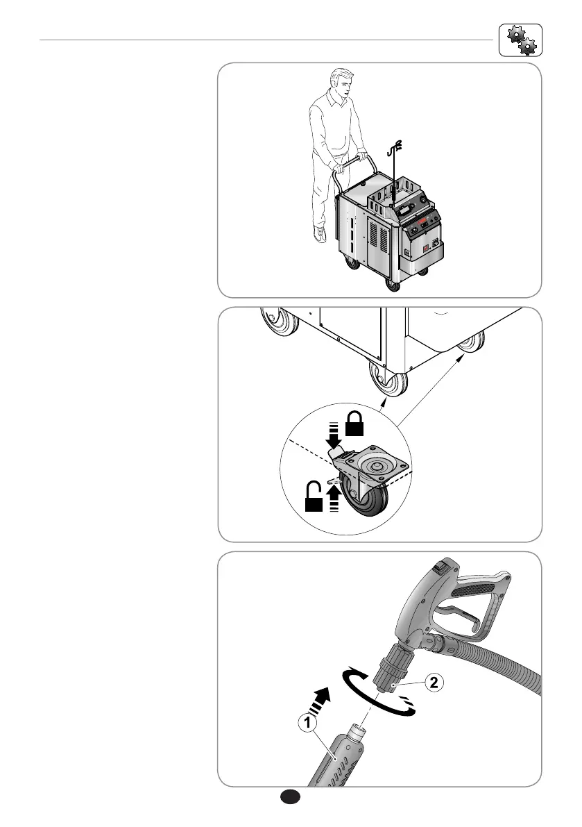
Fig. 13
Screw on the selected acces-
sory (1) to the grip of the hose
making the ring nut (2) turn as
demonstrated in Fig. 15.
To move the machine, push it
from behind as shown in f gure
Fig. 13.
In order to avoid unintended
movement of the machine, act
on the blocking levers present
on the front wheels (Fig. 14).