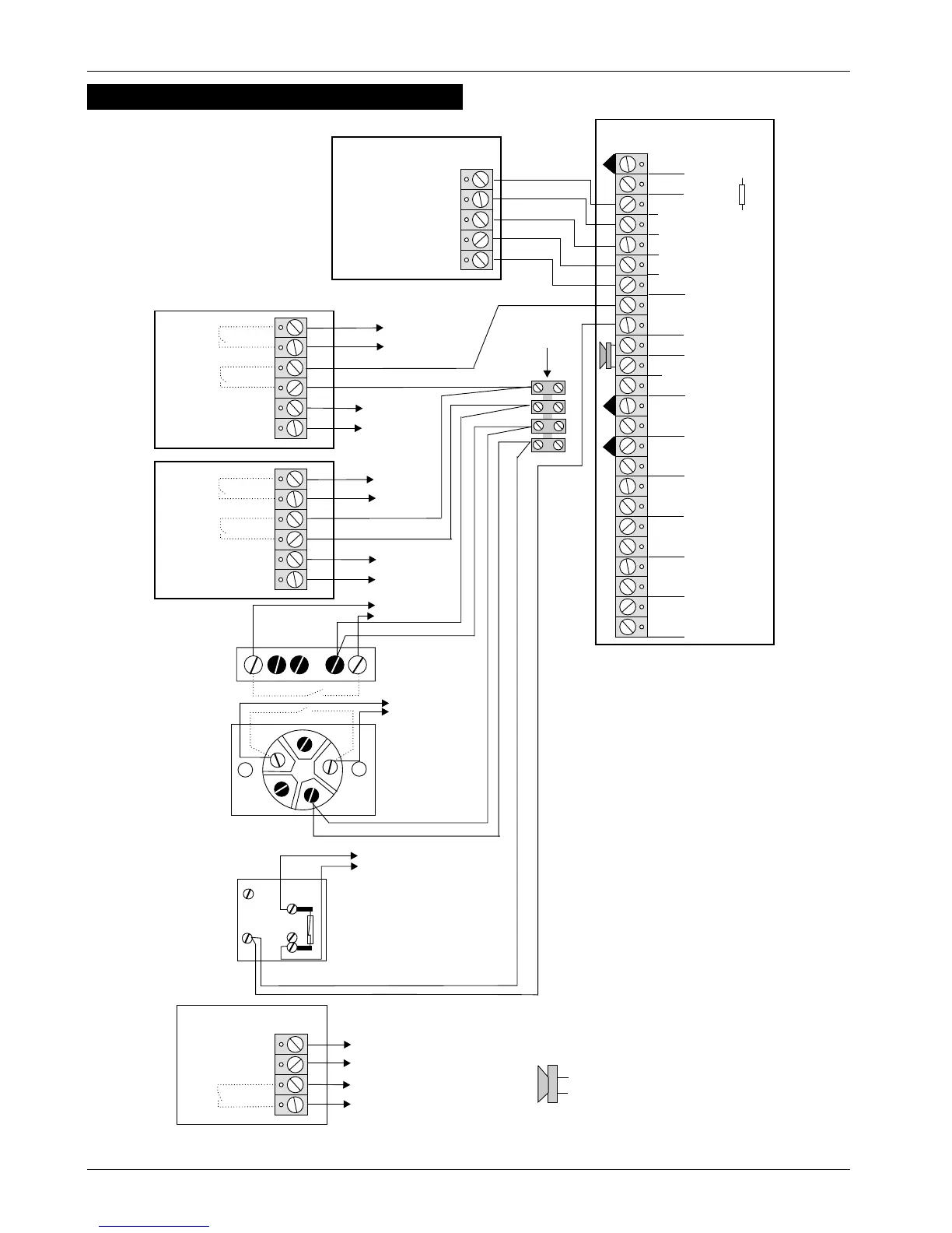
Wiring Example
TS400 & TS410 4of10 496522 Issue A
TS400 & TS410
ALARM
Supply +
Supply -
SMOKE DETECTOR
TAMPER
0V
+12V
PIR
TAMPER
ALARM
0V
+12V
PIR
To AUX +12V
To AUX -12V
To ZONE 4 (FIRE)
P. A. BU T TO N
To ZONE 5 (P.A.)
FLUSH CONTACT
SURFACE CONTACT
To FINAL EXIT
To ZONE 3
To AUX -12V
To AUX +12V
To ZONE 2
To AUX -12V
To AUX +12V
To ZONE 1
TRIGGER -
STROBE -
HOLD OFF +
HOLD OFF -
TAMPER RETURN -
EXTERNAL SOUNDER
ALM -
RST -
TRG -
STB -
+
-
H/O
TMP -
AUX
TAMPER
L/S -
+
-
AUX 12V
ZONE 5 (P A)
ZONE 4 (FIRE)
ZONE 3 (K/Sw)
ZONE 2 (ACCESS)
ZONE 1 (ACCESS)
FINAL EXIT
TS400/TS410
NOTE:
Any unused zones must be
linked out.
PIRs and Surface Contacts may
be connected to any zone. This
diagram is only used to represent
a typical installation example.
If a keyswitch is fitted, it must be
connected to Zone 3 and then
programmed as KEYSWITCH.
If a Smoke/Heat Detector is fitted,
it must be connected to Zone 4
and then programmed as FIRE.
If a P.A. Button is fitted, it must be
connected to Zone 5 and then
programmed as P.A.
= 16 Ohm Extension Loud speaker
(cut R37 to reduce volume)
TERMINAL STRIP
(NOT SUPPLIED)
R37
ALARM
Figure 2 Example Wiring Diagram