Do you have a question about the Menvier Security TS590 and is the answer not in the manual?
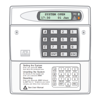
General introduction to the TS590 alarm system, its applications, and capabilities.
Details about the TS590 control panel's facilities, including detection circuits and outputs.
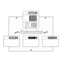
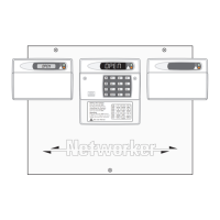
Information on connecting and types of remote keypads supported by the TS590.
Introduction to the TS700 Local Expansion Card (LEC) for zone expansion.
Information on the LEC6 6-zone expansion module and its configuration.
Detailed specifications for the TS590 control panel, including power and dimensions.
Specifications for the LCD remote keypad, including display and power requirements.
Specifications for the TS700 Local Expansion Card (LEC), including dimensions and current draw.
Specifications for the LEC 6 module, detailing zones, outputs, and dimensions.
Guidelines for routing alarm system cables, ensuring separation from mains and telephone lines.
Wiring instructions for connecting remote keypads and LECs to the network.
Step-by-step guide for mounting and securing the TS590 control panel.
Diagram and explanation of the TS590 main PCB, identifying key terminals and components.
Explanation of terminal blocks (SELV/TNV) and indicators on the control panel PCB.
Instructions for safely connecting the mains power supply to the control panel.
Instructions for connecting the standby battery and understanding battery fault indications.
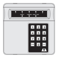
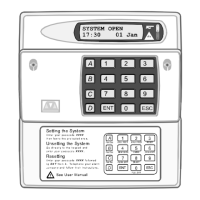
Overview of the two types of remote keypads supported by the TS590 system.
Details on remote keypad PCB layouts and jumper/switch functions.
Step-by-step guide for installing remote keypads, including mounting and wiring.
Wiring instructions for connecting a single 16 Ohm loudspeaker to a NETLCD keypad.
Procedure for converting a standard remote keypad into an engineer's keypad.
Steps for installing the TS700 LEC, including mounting and connecting.
PCB layout and connection details for the LEC 6 zone expansion module.
Step-by-step guide for installing the LEC 6 module, including mounting and wiring.
Explanation of wiring detection circuits using End Of Line (EOL) or Double Pole (DP) methods.
Detailed explanation of the End Of Line (EOL) wiring method for detection circuits.
Wiring terminals for connecting external sounders and strobes to the control panel.
Instructions for connecting extension loudspeakers to the control panel.
Connecting digital communicators (Digicom/RedCARE STU) to the control panel.
Installation of plug-on digital communicators for alarm status transfer.
Information on connecting compatible printers, including DATAC/RS232 types.
Essential checks to perform before powering up the alarm system for the first time.
Steps for the initial power-up of the system, including factory reset.
Checks to perform after initial system power-up to ensure correct operation.
Default settings stored in the Non-Volatile Memory (NVM) for various system parameters.
Overview of Engineer's Menu 1, accessed via engineer's passcode.
List of options and their corresponding pages within Engineer's Menu 1.
List and descriptions of programmable output types for keypads and digicom outputs.
Procedure for programming the TS590's detection circuits and their response.
Descriptions of available circuit types and how they respond when triggered.
Explanation of circuit attributes that can be assigned to alter operation.
Detailed explanation of various system timer settings and their functions.
Configuration options for system setting modes (Final Exit, Timed Exit, etc.).
Instructions on how to obtain a printout of all system parameters.
Configuration of the remote reset algorithm for overriding engineer resets.
General configuration options that affect system behavior and features.
Procedure to access User Menu 1 from Engineer's Menu 1.
How to view programmed location text messages from Engineer's Menu 1.
Procedure for relearning hardware after system configuration changes.
Overview of Engineer's Menu 2, accessed from Engineer's Menu 1.
List of options and their corresponding pages within Engineer's Menu 2.
Viewing the status and resistance of individual detection circuits.
Procedure for setting the system time in 24-hour format.
Procedure for setting the system date in day/date/month format.
Changing the engineer's personal 4-digit passcode.
Programming circuits to generate a chime sound.
Assigning circuits to shunt groups for isolation.
Printing selected events from the system's event log.
Configuring part set modes, including arming and omitting circuits.
Viewing the system event log, with options to scroll and alternate information.
List and description of various log event codes recorded by the system.
Procedure to reset the master user code to its factory default.
Initiating a remote call back sequence for data exchange with a remote site.
Editing custom text messages for circuits, banner, and location.
Accessing and configuring modem options, including call back numbers.
Programming the modem site number for remote communication security.
Setting the modem password for secure remote communications.
Testing digicom channels and outputs on the main PCB.
Procedure for resetting the digi-modem to re-establish communication.
Format and details of Point ID extended reporting for circuit and user data.
Procedure to reset the engineer's passcode if forgotten or changed incorrectly.
An example of configuring part set modes for different areas of a house.
Explanation of alarm abort functionality and sequential confirmation.
Steps and user types for setting up new users on the TS590 alarm system.
Detailed descriptions of available user types (Master, Standard, Holiday, etc.).
A quick reference guide to options and pages in Engineer's Menu 1.
A comprehensive list of programmable output types available for the system.
A quick reference guide to options available in User Menus 1 and 2.
| Brand | Menvier Security |
|---|---|
| Model | TS590 |
| Category | Control Panel |
| Language | English |