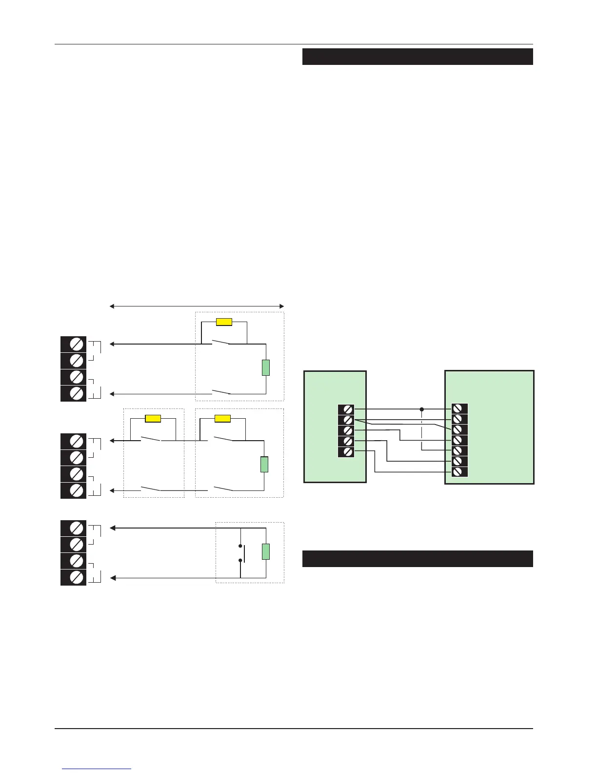
End Of Line
The EOL method requires the following:
l
The detector alarm contacts must have a 4K7
shunt resistor fitted.
l
A 2K2 End of Line (EOL) resistor must be fitted at
the point in the circuit furthest from the control
panel.
l
Loop resistance with the EOL resistor shorted
must be less than 100 Ohms.
l
The maximum number of detection devices
allowed in a circuit is ten.
l
Normally open devices such as pressure pads
and exit terminator buttons are connected
across outer terminals
l
If the detection circuit is not used links can be
fitted across the zone and tamper loops or
programmed as Not Used.
External Sounder Connections
The following terminals have been provided to
allow connections to an external sounder:
H/O - This is used to provide a permanent -ve
hold off to external sounders, strobes etc.
H/O + This is used to provide a permanent +ve
hold off to external sounders, strobes etc.
It is protected by a 1 Amp fuse (Bell 12V).
TR - This is the negative tamper return
connection from the siren or bell.
STB - This is the strobe output which will switch to
0V on alarm and is rated at 500mA.
Connect the other side of the strobe to
the H/O +.
TRG - This is the bell trigger output which can be
programmed for SAB or SCB operation, as
follows:
SAB: TRG - will switch to 0V on alarm and
will provide a maximum of 500mA.
SCB: TRG - will provide a negative hold
off (500mA), which is removed on alarm.
Auxiliary Tamper
These two terminals provide tamper protection to
auxiliary devices such as power supplies,
extension loudspeakers etc. If they are not used
they must be linked out.
16
System Installation TS590 Installation Manual
500 metres or 100 Ohms
Alarm
Alarm
Tamper
Max. 10 devices per circuit
Wiring N.O. devices (Exit Terminators)
Tamper
4K7 = Yellow, Violet, Red
2K2 = Red, Red, Red
Alarm
Tamper
4K7
4K7
4K7
2K2
2K2
2K2
CIRCUIT B
ZB
TB
CIRCUIT B
ZB
TB
CIRCUIT B
ZB
TB
Figure 13. End of Line Wiring
Typical
External Sounder
Control
Panel
H/O +
12V +
H/O -
0V
Tamper In
TR -
STB -
Tamper Out
TRG -
Strobe +ve
Strobe -ve
Trigger -ve
Figure 14. External Sounder Connections
 Loading...