Overview
Introduction
The TS590 alarm control system has been
designed to suit small to medium installation sites.
The TS590 system can monitor 6 zones locally and
up to 14 zones via remote keypads or LECs. All
zones can be wired either as double pole or end
of line.
The TS590 features local “downloading" via a DCI
link and PC, or remote “downloading” via a
plug-on digi-modem (DC58M) and PC.
Control Panel
The control panel is the controlling unit for the
system, it has a power supply and connections for
a standby battery. It has the following facilities:
l
6 programmable detection circuits
l
Bell and strobe outputs
l
5 programmable digicom/RedCARE outputs
l A connector for a plug-on digi-Modem
l
Extension loudspeaker output
l
All system program information and the 700
event log is stored in a removable non-volatile
memory (NVM)
l
15 user codes + engineer's code
l
7.0Ah battery capacity
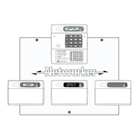
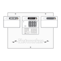
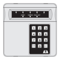
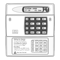
Remote Keypads
Up to 4 remote keypads can be connected to the
control panel. All remote keypads have “Power
LED” and a programmable “Function LED” (the
“Function LED” may be programmed as “Fault” or
“Area Set” etc.). When using the keypads the text
for user codes, part setting modes and circuit
identification can be programmed to make the
operation and programming of the system easier.
There are two types of remote keypads that can
be used:
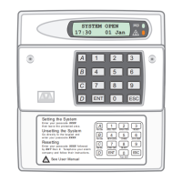
32 Character LCD (NETLCD)
The NETLCD remote keypad has two detection
circuits and a single switched -ve output. The
NETLCD also has a backlit 32 character super-twist
Liquid Crystal Display (LCD) and a backlit tactile
rubber keypad.
32 Character LCD
The LCD remote keypad has a backlit 32
character super-twist Liquid Crystal Display (LCD)
and a backlit tactile rubber keypad. This keypad
has the same user interface as the NETLCD, but
does not provide any zones.
TS700 LEC
The Local Expansion Card (LEC) provides two
programmable detection circuits and one
programmable output.
LEC6
The 6 zone LEC provides the facility to add up to 6
additional zones. The 6 zone LEC has a jumper
which allows it to be configured for 6 zone
expansion or 4 zone expansion. The table below
shows the circuits that are allocated for both
jumper settings.
JP1 = 2-4 (A-F) JP1 = 3-4 (C-F)
Circuits 9 - 14 Circuits 11 - 14
4
Overview TS590 Installation Manual