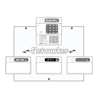
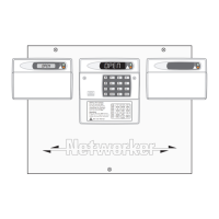
Part-Set Application Example
This application example shows how to configure
the part set buttons to set different areas of a 3
bedroom house.
Using the drawing of a typical 3 bedroom house,
the following part set modes are required:
Part Set A Circuits 01 through to 08 armed
and circuits 09 and 10 omitted.
Part Set B Circuits 01 through to 09 armed
and circuit 10 omitted.
Part Set C Circuits 01 through to 06 armed
and circuits 07 through to 10
omitted.
1. First create a table listing the circuits that are
required to be armed (A) and omitted (O) for
each part set mode:
Circuit Location P-Set A P-Set B P-Set C
01 Front Door A A A
02 Hallway detector A A A
03 Hall door to garage A A A
04 Garage door A A A
05 Garage back door A A A
06 Kitchen door A A A
07 Dinning room PIR A A O
08 Lounge PIR A A O
09 Bedroom 2 PIR O A O
10 Landing PIR O O O
2. From the above table, program circuits 01-10
as omitted or armed for each part set mode
(see “Configure Omits” on page 38).
+
Circuit 02 (Hallway detector) must be
programmed as a “Night” circuit with the
“Entry” attribute. This will ensure that the
entry timer is started when the
occupants come downstairs to unset the
system.
Alarm Abort & Confirmation
The TS590 supports “Alarm Abort” and “Sequential
Confirmation”. The alarm abort can be achieved
by either sending an abort signal on a dedicated
channel or by restoring the alarm channel.
Alarm Abort Operation
When the alarm is triggered the system transmits a
channel 3 (Alarm) to the ARC. If the system is unset
within the “Abort Delay” period the abort output is
triggered and an Abort signal is transmitted to the
ARC. The alarm output is also restored.
Sequential Confirmation Operation
When the first alarm is triggered, the system
transmits channel 3 (Alarm) to the ARC. If a
different zone is activated the system transmits
second alarm signal to the ARC.
1. If the Digicom is being used program the
digicom channels as shown below, see “Digi
Channels”, on page 22. If a stand-alone
digicom is being used program the digicom
outputs as shown below, see “Digi Outputs”, on
page 22.
Channel No Output Type
3 005 (Alarm)
4 043 (Abort)
5 011 (Second Alarm)
2. Program the “Abort Delay” timer to the required
time (the default is 180 seconds), see “System
Timers”, on page 27.
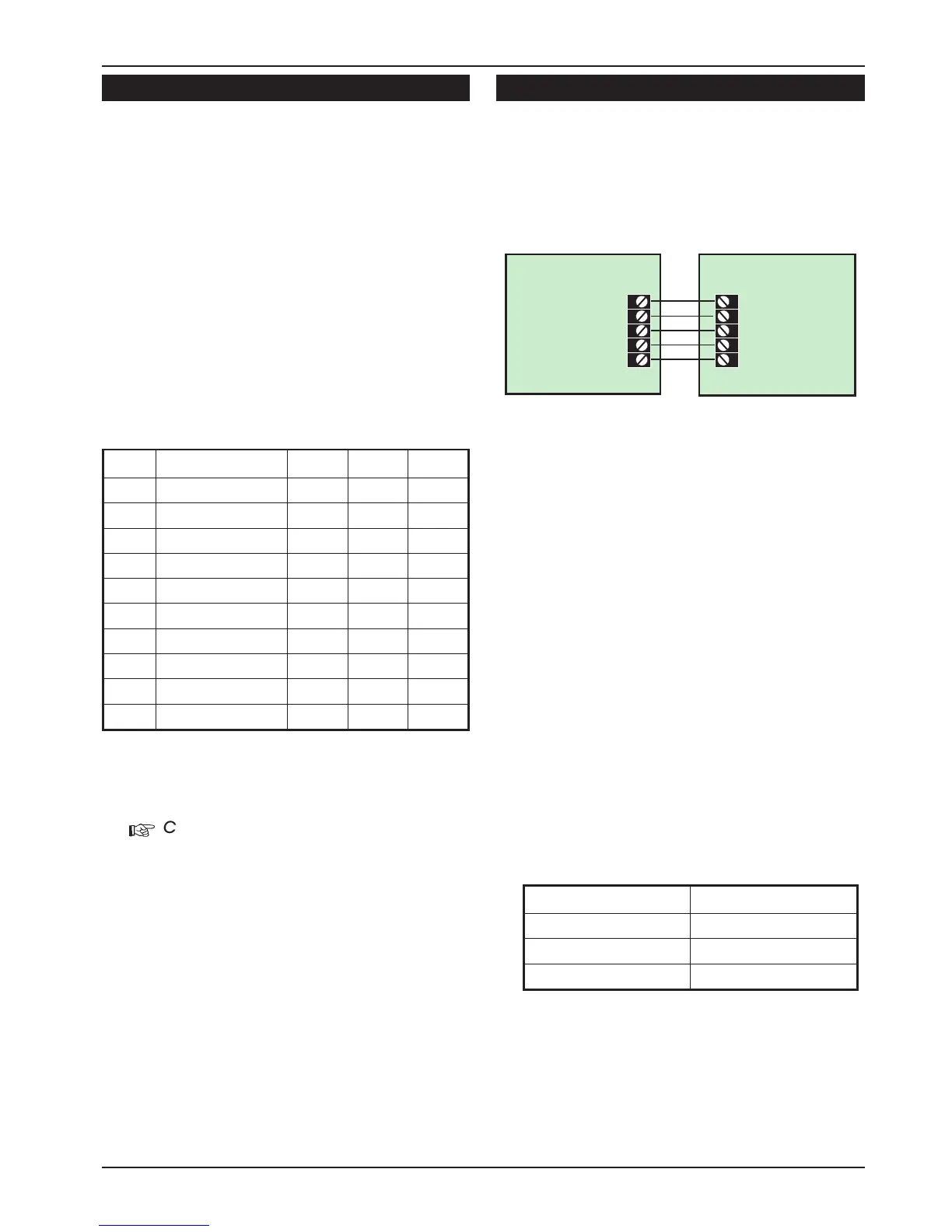
47
TS590 Installation Manual Appendices
+12V
+DC POWER
Digicom
(stand-alone)
0V
0V
3 - Alarm
Alarm (005) - 3
8 - Abort
Abort (043) - 4
7 - Confirmation
Second Alarm (011) - 5
TS590
Figure 20. Alarm Abort & Sequential Confirmation
 Loading...