DC54 & DC58M Installation
A plug-on digital communicator DC54, DC58 or
DC58M may be fitted inside the control panel to
allow alarm status information to be transferred to
a dedicated central station. The unit should be
fitted in accordance with the installation
instructions supplied with it and connected to the
control panel plug DIGI-MODEM (JP3) using the
lead provided with the unit. The NVM within the
communicator will need to be programmed
using an engineer’s keypad or PP5.
Connecting a Printer
The TS590 supports two type of printers, the CPA6
printer (no longer available) and any standard
RS232 printer. When using an RS232 printer a
DCI/MPA printer adaptor will be required. Menvier
Security supply a DATAC printer kit which consists of
a portable RS232 printer, charger unit and DCI
adapter.
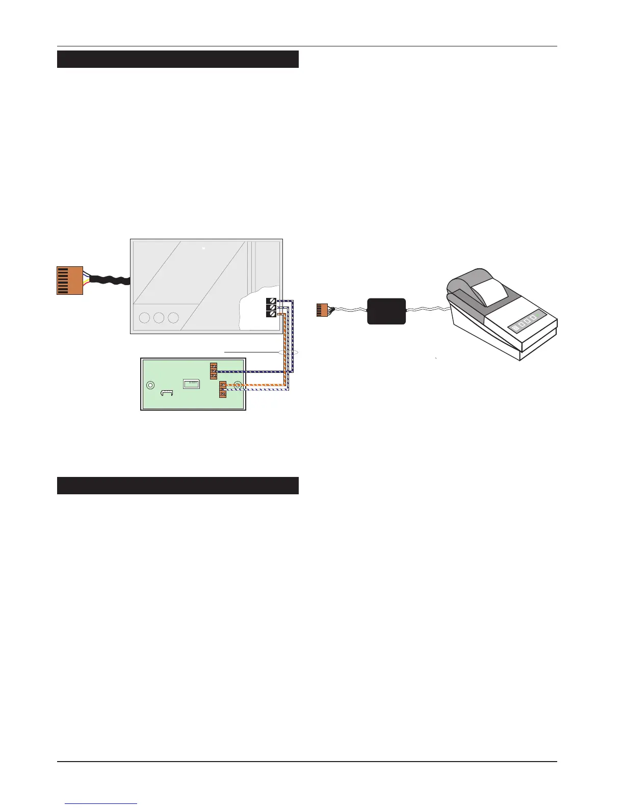
Using the DATAC / RS232 Printer
1. Plug the DCI/MPA on to the PRINTER plug (JP1)
on the main control panel PCB.
2. Plug the other end of the DCI/MPA into the
DATAC or RS232 printer.
3. In order for the printer to work correctly ensure
that the printer is set to the following:
Baud rate = 4800
Parity = None
Start bits = 1
Stop bits = 2
Data bits = 8
DTR = Normal
4. When setup correctly the system program
details and event log can be printed.
5. When finished unplug the MPA/DCI. If the
printer is left connected events will be printed
as and when they occur.
18
System Installation TS590 Installation Manual
Connect to JP3
DIGI-MODEM
Plug-on digicom / digi-modem
A
B
BC
B.T. master jack ( Type NTE5
user accessible connections )
A(5) = White / Blue ring
BC(3) = Orange / White ring
B(2) = Blue / White ring
Telephone cable
(Type 1/0.5mm CW1308)
6
5
4
3
2
1
Figure 17. DC54/DC58 Connections
MPA
or DCI
DATAC or RS232 printer
RS232 Data
Connect to JP1
PRINTER
1
Figure 18. Printer Connections
 Loading...