Do you have a question about the Menvier Security TS790+ and is the answer not in the manual?
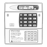
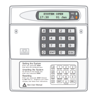
Describes TS790+/TS900+ alarm control units for medium to large installations.
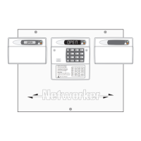
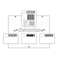
Details the system's structural components, including control panel and network architecture.
Covers zones, expansion capabilities, and remote keypad types.
Details power requirements, consumption, and mains input.
Provides dimensions and weights of control panels and remote keypads.
Guidelines for laying and managing cables for detection and network connections.
Wiring instructions for XNodes on TS900+ systems using 4-core cable.
Wiring for remote devices using 6-core cable in star or daisy-chain configurations.
Wiring remote keypads after XNodes using an 8-core cable.
Step-by-step guide for mounting and securing the control panel back box.
Diagram and explanation of the main PCB connections and components.
Details jumper plugs, terminals, and indicator LEDs on the main PCB.
Instructions for connecting the main power supply to the system.
How to connect the standby battery for power failure operation.
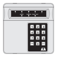
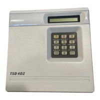
Overview of available remote keypad types and their features.
Steps for connecting and configuring remote keypads.
How to use a remote keypad as an engineer's interface for programming.
Details the XNode's functions, wiring, and programmable outputs.
Diagram showing XNode connections, terminals, and outputs.
Steps for fitting and connecting an XNode to the system.
Installation instructions for the obsolete TS900 Node.
Steps for installing the Local Expansion Card (LEC).
Methods for wiring detection circuits: End of Line (EOL) or Double Pole (DP).
Details the Double Pole wiring method for detection circuits.
Details the End of Line wiring method for detection circuits.
Terminal descriptions for connecting external sounders and strobes.
Wiring external sounders using XNode programmable outputs.
Tamper protection for auxiliary devices like power supplies.
Connecting and controlling extension loudspeakers.
Connecting digital communicators and RedCARE STU.
Fitting plug-on digital communicators for remote reporting.
Installing output modules for circuit status indicators.
How to connect and use printers with the system.
Setup instructions for DATAC or RS232 printers.
Overview of programmable output functions and types.
List and description of control panel programmable outputs.
Details programmable outputs for XNodes.
Programmable output on remote keypads and LECs.
Using 519XB with 519FM for power supply monitoring.
Checks to perform before initial system power-up.
Steps for first-time system power-up and initial checks.
Post-initial power-up checks for system operation and voltage.
Table of default NVM settings for system parameters.
Overview of Engineer's Menu 1 and how to access it.
Lists available options and their corresponding page numbers.
Programming control panel and remote keypad outputs.
Programming digicom outputs on the control panel PCB.
Programming the 8 plug-on digicom channels.
Lists and describes various programmable output types.
How to program detection circuits and their response.
Defines available circuit response types like Night, Fire, etc.
Defines attributes that alter circuit operation (e.g., Access, Double Knock).
Overview and list of system timers for delays and durations.
Configures system setting modes for different scenarios.
How to obtain a printout of system parameters.
Configuration for the remote reset facility.
System configuration options for various features.
Overview of Engineer's Menu 2 and how to access it.
Lists available options and their corresponding page numbers.
How to view the status and resistance of detection circuits.
Setting the system time on remote keypads.
Setting the system date on remote keypads.
How to change the engineer's passcode.
Programming circuits to function as chimes.
Assigning 24hr/Auxiliary circuits to groups.
Printing system log events to a connected printer.
Splitting the system into four wards (areas) for zone management.
Viewing the system log events, allowing scrolling through logs.
Overview of Engineer's Menu 3 and how to access it.
Lists available options and their corresponding page numbers.
Programming three programmable time switches for automated control.
Defining part-set buttons and their ward assignments.
Defining code set groups and their ward assignments.
Assigning a 7-character name to user 00.
Assigning 32 characters of text to each part set group.
Assigning up to 16 characters of text to detection circuits.
Editing custom text messages for reset, banner, and location.
Programming a 32-character location message for the control panel.
Programming a 32-character message for printer headers.
Setting a 16-character banner message for the part-set display.
Programming the two outputs on each XNode.
Accessing diagnostic routines like current consumption and voltage.
Displaying the battery charging voltage at the control panel.
Measuring the resistance of individual detection circuits.
Testing digi channels and outputs programmed for specific functions.
Viewing circuits with the 'Flagged' attribute not activated.
Programming custom outputs using logic circuits.
Accessing and configuring modem options like call back numbers.
Flowchart for programming digicom settings and parameters.
Procedure to reset the digicom device for log-on.
New format for reporting circuit data using Contact ID.
Procedure to reset the engineer's passcode if lost or forgotten.
Example of part-set configuration in a typical 3 bedroom house.
Method to configure part-set groups by omitting specific wards.
Method to configure part-set groups by arming specific wards.
Example of part-set configuration for commercial premises.
Using a keyswitch circuit for system control and setting.
Using time switches for automated system actions like arming.
System alarm abort and sequential confirmation features.
Process for adding and configuring new users with passcodes and types.
Reference list of all programmable output types and their functions.
| Brand | Menvier Security |
|---|---|
| Model | TS790+ |
| Category | Control Panel |
| Language | English |