Appendices TS790+ & TS900+ Installation Manual
58
Defining Part-Set buttons to Arm a
Ward(s)
This method of defining the part set groups
requires you to think of the system in terms of
separate areas of protection (Wards), then
configuring the part set groups so that different
combinations of wards are set.
1. From the previous part-set requirements
assign the different physical areas to wards,
e.g.:
Ward A: Downstairs perimeter detection (Circuits
01,04, 05 & 06).
Ward B: Downstairs Internal detection (Circuits
03, 07 & 08).
Ward C: Bedroom 2 (Circuit 09).
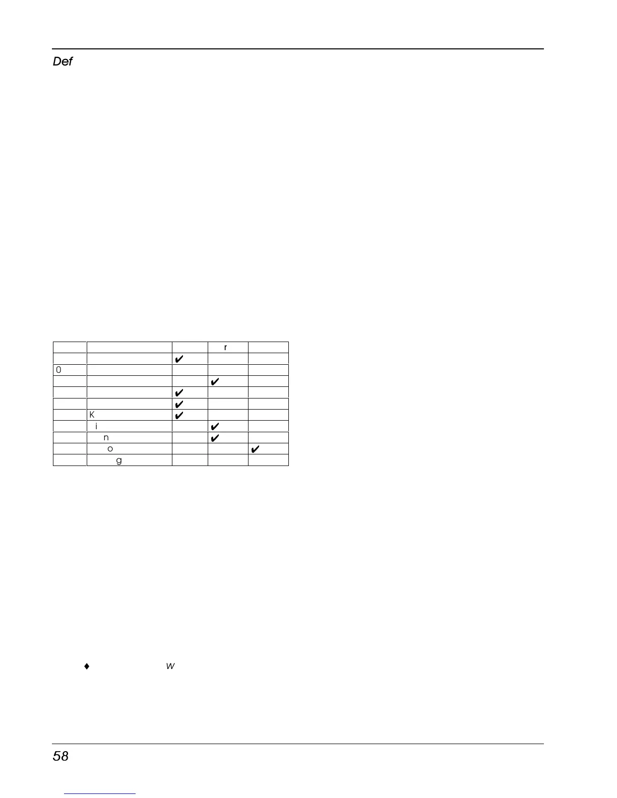
2. Using the above ward requirements create a
Table for assigning circuits to wards. Circuits
with no ticks are assigned to the “System
Ward”:
Circuit Location Ward A Ward B Ward C
01 Front Door
4
02 Smoke Detector
03 Hall door to garage
4
04 Garage door
4
05 Garage back door
4
06 Kitchen door
4
07 Dinning room PIR
4
08 Lounge PIR
4
09 Bedroom 2 PIR
4
10 Landing PIR
3. From the above Table assign circuits 01-10
to their relevant wards (see “Configure
Wards” on page 41).
4. Program the part set groups, see “Part set
Groups”, on page 47. This ensures that when
the user selects button A, B or C the system
arms the correct wards. When using this
method, the part set groups are
programmed as follows:
Part Set Group A: [ AB ]
Part Set Group B: [ ABC]
Part Set Group C: [ A ]
¨
This method will only work correctly if
circuits are assigned only to one
ward. If a circuit is assigned to more
than one ward, it will only be armed
when all the wards its assigned to are
set.