TS790+ & TS900+ Installation Manual Engineer’s Menu 3
51
Custom Outputs A & B [3.A/B]
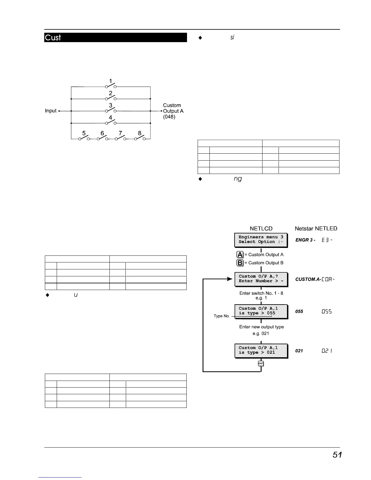
These options allows the engineer to program
both custom outputs. The diagram below
represents the logic circuit for the custom
output.
Each switch in the diagram represents a
programmable output type, therefore the
custom output will only activate when the
correct combination of output types are active.
Switches 1 - 4 perform a logical “OR” function
and switches 5 - 8 perform a logical “AND”
function.
Custom Output - Example 1
This example shows how the “OR” function can
be used so that the “Custom Output” activates
when circuit 0001 or 0005 or 0016 causes an
alarm condition. The table below shows how
each switch is programmed to achieve this.
OR AND
1 Circuit 001 Alarm 5 Always Off
2 Circuit 0005 Alarm 6 Always Off
3 Circuit 016 Alarm 7 Always Off
4 Always Off 8 Always Off
¨
When using the “Custom Output” for “OR”
logic only, all unused switches must be
programmed to the type “Always Off”.
Custom Output - Example 2
This example shows how the “AND” function can
be used so that the “Custom Output” only
activates when the system is ward A is set and
time switch A is active. The table below shows
how each switch is programmed to achieve
this.
OR AND
1 Always Off 5 Ward A Set
2 Always Off 6 Time Switch A
3 Always Off 7 Time Switch A
4 Always Off 8 Time Switch A
¨
When using the “Custom Output” for “AND”
logic only, switches 1-4 must be
programmed to the type “Always Off” and
any of the unused “AND” switches must be
programmed to the same type as one of the
used switches.
Custom Output - Example 3
This example shows how to use both the “AND”
and “OR” functions so that the “Custom Output”
activates when ward A is set and time switch A
is active or when the courtesy light output is
active. The table below shows how each switch
is programmed to achieve this.
OR AND
1 Courtesy Light 5 Ward A Set
2 Always Off 6 Time Switch A
3 Always Off 7 Time Switch A
4 Always Off 8 Time Switch A
¨
When using the “Custom Output” for “AND”
and “OR” logic, any of the unused “OR”
switches must be programmed to the type
“Always Off” and any of the unused “AND”
switches (5-8) must be programmed to the
same type as one of the used switches.
Custom Outputs Flowchart