WIRING DIAGRAMS
90-883728 JULY 2001 Page 2D-33
FUEL TANK CALIBRATION:
NOTE: There are three methods to set up fuel tank level monitoring feature:
First: Do nothing. Linear readout based on raw sensor values. This mode does not factor
in irregular tank shapes.
Second: By following the tank calibration procedure described on pages 33–35, but with-
out actually adding fuel. System Monitor will supply an estimated range value based on
linear interpolation of the sensor range values. This mode does not factor in irregular tank
shapes.
Third: By following the tank calibration procedure described on pages 33–35 completely
System Monitor will display an estimated range value that factors in the tank shape.
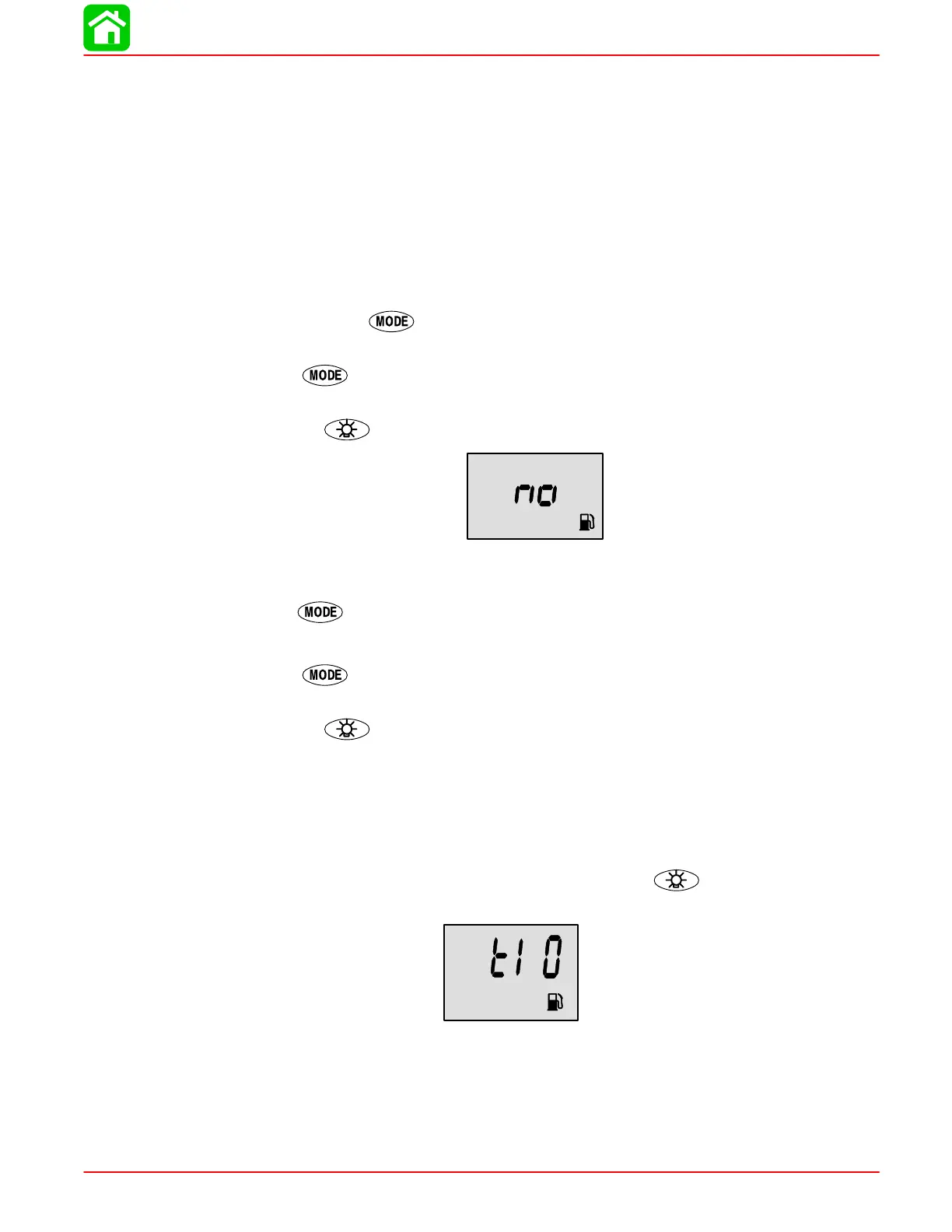
1. Scroll using the key until you see “t1”. This tells you that you have entered tank
1 calibration.
2. Press once more.
3. You will see the word “no” and the gas tank icon. Enter the capacity of tank 1 in gallons
using the
key.
NOTE: The word “no” will not go away unless the gauge sees a tank connected to the system.
With no tank connected you will not be able to enter a capacity.
4. Press once more.
5. You will see “t2”. This tells you that you have entered tank 2 calibration.
6. Press
once more.
7. You will see the word “no” and the gas tank icon. Enter the capacity of tank 2 in gallons
using the key.
NOTE: The word “no” will not go away unless the gauge sees a tank connected to the system.
With no tank connected you will not be able to enter a capacity.
NOTE: Tank 2 does not have to be a fuel tank. It could represent an oil tank for example. See
page 35 for tank 2 selection.
Select whether you want to calibrate the fuel tank “t1”. (The gauge will not let you calibrate
the fuel tank until the capacity had been entered). Press the
button to select 0= off or
1= on.
 Loading...


