4000 MPC GEN 2 PISTOL GRIP REMOTE CONTROL INSTALLATION/OPERATION INSTRUCTIONS
90-899782001 APRIL 2008 Page 13 / 23
2. Allow sufficient slack in the trim switch leads to permit free movement through the full
range of the control handle motion. Do not restrain the trim switch leads with cable
ties.
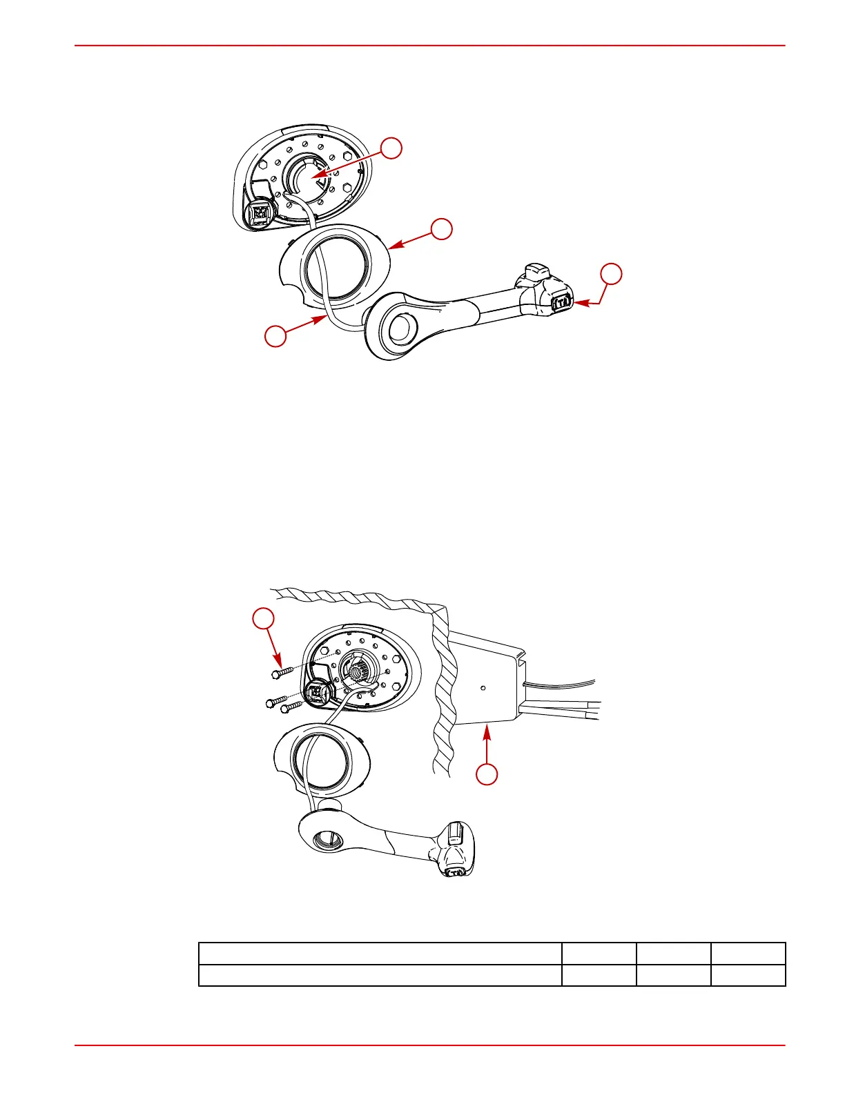
a - Bezel opening
b - Trim switch
c - Trim leads
d - Bezel cover
IMPORTANT: Ensure the trim switch leads are not pinched when mounting remote
control module to the bezel. The trim switch leads must be free to move with the full range
of the control handle motion.
3. Install the remote control module to the bezel. Secure the remote control module with
three screws. Tighten the screws to the specified torque.
a - Control module mounting screw (3)
b - Control module
Description Nm lb. in. lb. ft.
Control module mounting screw (3) 5.6 50
 Loading...