CYLINDER HEAD
90-857138R1 MAY 2000 Page 4A-9
3. Rotate flywheel until raised mark on camshaft is visible through fuel pump hole and
notched mark on flywheel aligns with TDC mark on block casting. Piston is now at top
dead center and valve clearance may now be checked with feeler gauge.
a
b
c
d
e
a-Raised Mark on Camshaft
b-Notched Mark on Flywheel
c-TDC Mark
d-5° BTDC Mark on Block Casting
e-25° BTDC Mark on Block Casting
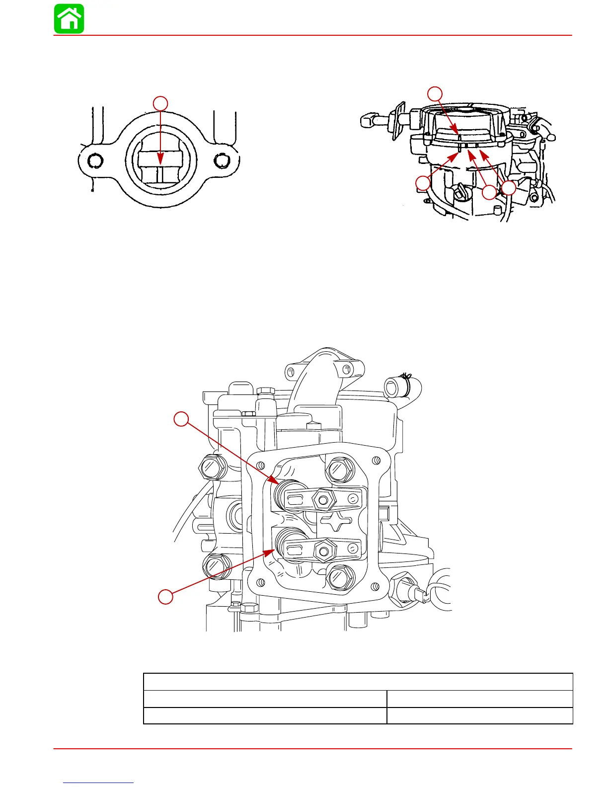
4. Measure valve clearance with a feeler gauge. Adjust if out of specification.
57250
a
b
a-Intake Valve
b-Exhaust Valve
Valve Clearance (Cold)
Intake 0.002 - 0.005 in. (0.06 - 0.14 mm)
Exhaust 0.004 - 0.007 in. (0.11 - 0.19 mm)
 Loading...