Powerhead
Page 4A-18 90-8M0065421 NOVEMBER 2012
Description Nm lb‑in. lb‑ft
Fuel tank mounting bolts (M6 x 25) (3) 6 53
Valve Clearance Adjustment
IMPORTANT: Adjust the valve clearance while the engine temperature is cool.
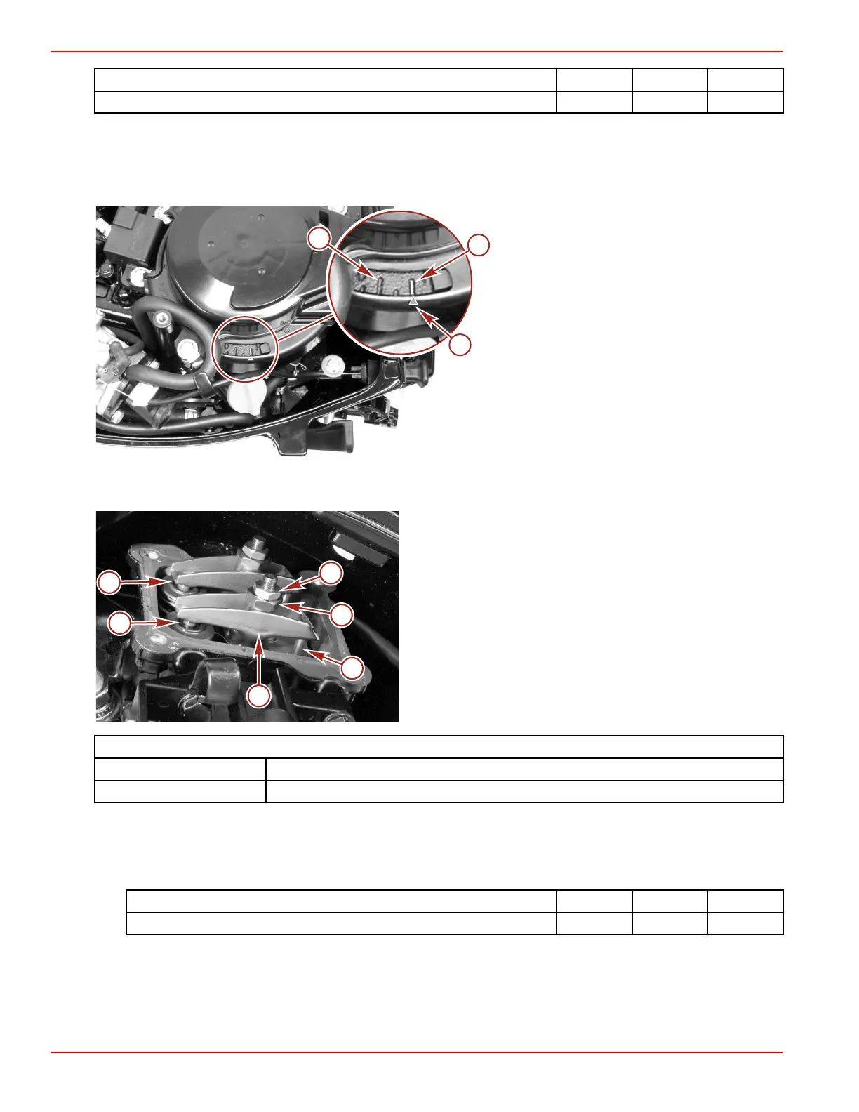
1. Align the timing mark on the flywheel to 0° TDC on the compression stroke. The piston is at top dead center and both
valves are closed. The valve clearance may now be checked.
a - 0° flywheel timing mark
b - Pointer on flywheel cover
c - 10° BTDC flywheel timing mark
2. Remove the spark plug lead and the cylinder head cover.
3. Measure each valve clearance with a feeler gauge.
a - Nut
b - Pivot
c - Push rod
d - Rocker arm
e - Intake valve
f - Exhaust valve
Valve to Rocker Arm Clearance
Intake 0.06–0.14 mm (0.0024–0.0055 in.)
Exhaust 0.11–0.19 mm (0.0043–0.0075 in.)
4. Adjust if out of specification.
a. Hold the pivot and loosen the nut.
b. Adjust valve clearance by rotating the pivot.
c. When the proper clearance is achieved, hold the pivot and tighten the nut to the specified torque.
Description
Nm lb‑in. lb‑ft
Rocker arm nut 11 97
d. Recheck valve clearance.
5. Clean the cylinder head and cover surface.
6. Install a new gasket.
7. Attach the cylinder head cover to the cylinder block with four bolts. Tighten the bolts to the specified torque.
 Loading...