MIE MODELS - HURTH TRANSMISSION
SERVICE MANUAL NUMBER 23
90-861326--1 MARCH 1999 Page 2D-5
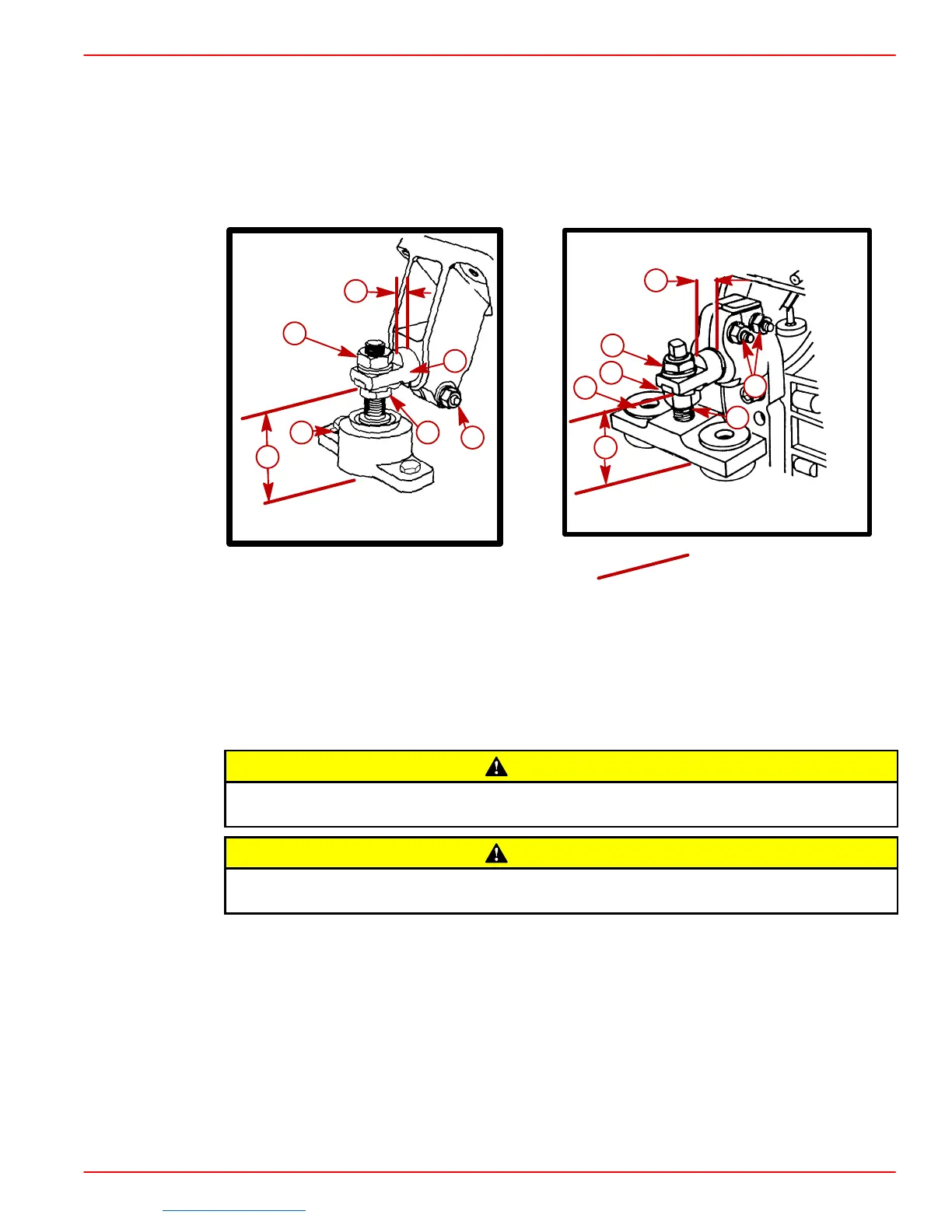
2. Ensure that all mounts are:
a. In the center of their up and down adjustment.
b. Mounting hole, which is a slot, is forward (if so designed; new style is not slotted).
c. Large diameter of mount trunnion extended as shown.
d. Each mount base is downward. Tighten clamping bolts and nuts slightly to prevent
moving in or out. Mounts must be free to pivot when installing engine.
72638
70158
a
b
c
d
e
g
f
e
a
g
d
c
b
f
Front Mount - Typical Rear Mount - Typical
a-Locking Nut
b-Adjusting Nut
c-Trunnion Clamp Screw And Nut, With Lockwasher
d-Slot Forward
e-3/8 in. ± 1/16 in. (10 mm ± 2 mm)
f-2-5/8 in. ± 1/16 in. (67 mm ± 2 mm)
g-Mount Trunnion
CAUTION
Center lifting eye (located on top of thermostat housing) is used for engine align-
ment only. DO NOT use to lift entire engine.
CAUTION
DO NOT allow lifting sling to hook or compress engine components or damage to
them will occur.
3. Attach a suitable sling to lifting eyes on engine. (Refer to “Removal” section for
location of lifting eyes.)
IMPORTANT: Engine bed must position engine so that a minimum of 1/4 in. (6 mm)
up and down adjustment still exists on all four mounts after performing final align-
ment. This is necessary to allow for final engine alignment.
Downloaded from https://needmanual.com/!

 Loading...
