GENERAL SYSTEM DIAGNOSTICS SERVICE MANUAL NUMBER 23
Page 5E-42 90-861326--1 MARCH 1999
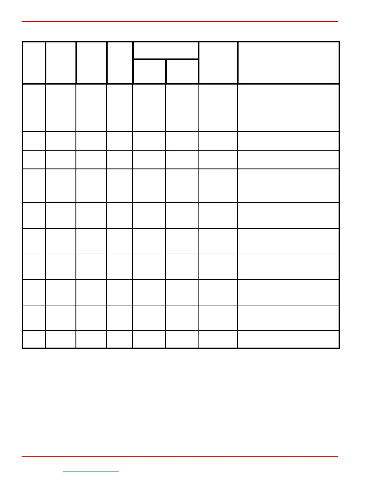
MEFI 3 - J-1 Circuits (continued)
Pin
Circuit
(CKT)
Normal Voltage
Diag-
nostic
Pin
Func-
tion
Num-
ber
(#)
Color
Ignition
ON
Engine
Running
Trouble
Codes
DTC(s)
Symptoms
J1-14
Knock
Sensor
Signal
(Only
used on
7.4L MPI)
496 BLU – – 43, 44
Poor Fuel Economy,
Poor Performance
Detonation
J1-17
Injector
Driver
468
DK
GRN
B+ B+ None Rough Idle, Lack Of Power, Stall
J1-20
ECM
Ground
450 BLK
0
(NOTE 5)
0
(NOTE 5)
None
Rough Running, Poor Idle, Lack
Of Performance
J1-23
Fuel
Pump
Relay
Driver
465
DK
GRN/
WHT
0
(NOTE
1&5)
B+ None No Start
J1-24
Ignition
Control
Bypass
424
TAN/
BLK
0
(NOTE 5)
4.5V 42 Lack Of Power, Fixed Timing
J1-26
Audio
Warning
Horn
29
DK
GRN
– – None –
J1-27
IAC
“B”
Low
444
GRN/
BLK
Not
Usable
Not
Usable
None
Rough Unstable or Incorrect
Idle
J1-28
IAC
“A”
High
441
BLU/
WHT
Not
Usable
Not
Usable
None
Rough Unstable or Incorrect
Idle
J1-30
Knock
Sensor
Signal
496 BLU – – 43, 44
Poor Fuel Economy,
Poor Performance
Detonation
J1-32
Serial
Data
461 ORN 5V 5V None
No Serial Data
(NOTE 6)
NOTE 1: Battery voltage for first two seconds, then 0 volts.
NOTE 2: Varies with temperature.
NOTE 3: Varies with manifold vacuum.
NOTE 4: Varies with throttle movement.
NOTE 5: Less than .5 volt (500 mV).
Downloaded from https://needmanual.com/!

 Loading...
