15
Meritor Differential Carrier 18X
2 Maintenance
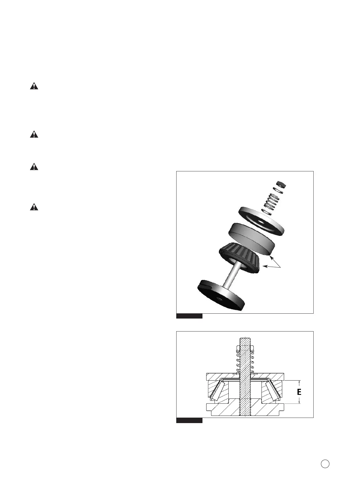
Fig. 2.3
Fig. 2.2
Bearing
Tool
MST4904
CAUTION:
Only original Meritor spare parts should be used.
Use of non-original parts could seriously affect differential
unit performance. Use of non-recommended lubricants will
adversely affect performance and service life.
WARNING:
Waste oil disposal must be carried out in conformity with the
legislation in force.
CAUTION:
Differential carrier removal and handling should be
performed using the specified lifting and carrying
equipment.
CAUTION:
During dismantling/reassembly operations always engage
differential lock to ensure alignment of the splined sections
and prevent shift fork bending and spline damage.
Finally, ensure that:
• There are no leakages from air lines.
• Lubricating oil meets manufacturer’s specifications.
• Differential lock cab warning lamp functions correctly.
Ring Gear & Pinion Adjustment
If a new ring gear and drive pinion are to be installed, the correct
thickness of shim pack required between the inner bearing cup
and the carrier must be determined.
When the correct shims pack has been identified, the bearing
preload on the drive pinion must be adjusted. The preload is
controlled by the thickness of the spacer between the inner and
outer cones of the pinion bearings.
Determining the Pinion Inner Bearing Dimension
Before assembling the carrier, measure the complete inner pinion
bearing assembly compressed into a suitable service tool
MST4904, as detailed below. Place the complete bearing into a
suitable service tool and rotate it while tightening the tool
(Fig 2.2).
Tighten the tool until the bearing is completely seated (Fig 2.3).
If the tool is not available press the bearing with 1.000 N or 100 kg
load and take measurement in three points - about 120 degrees.
Measure the internal distance between the service tool plates at
three equally spaced points to determine the total width of the
bearing E (Fig 2.3) (e.g. 58.10). Record dimension E as it is
required for Shim Pack calculation below.”