05/04
5
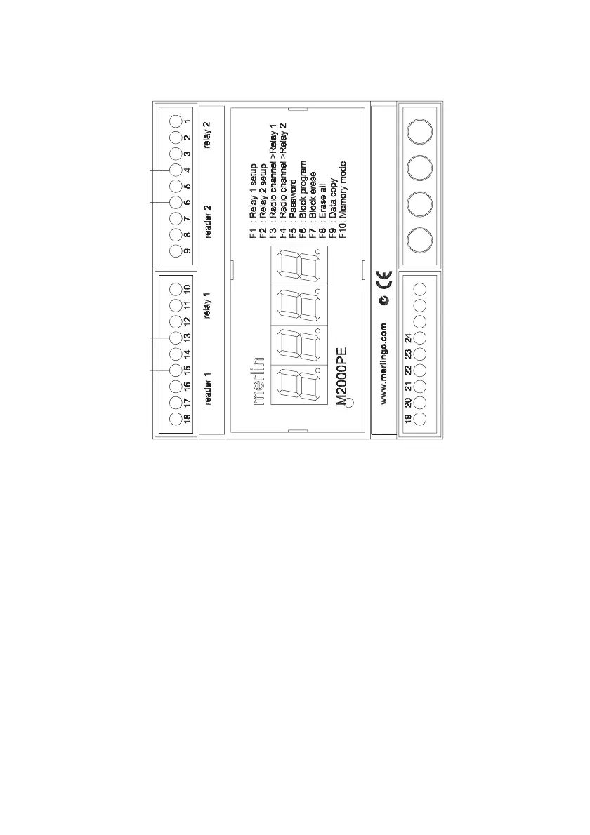
Connections
Note Make sure that terminals 4 & 6 and 13 & 15 are bridged if no enabling loop is used.
Whatever bridges these terminals must be Normally Closed in order for each relay to oper-
ate.
When connecting a Merlin aerial to the antenna terminal, cut off the MCX connector and
expose 20 mm of braid. Twist this and connect to the ‘antenna shield’ terminal. Connect the
centre core to the ‘antenna’ terminal. Take care to avoid short circuits from stray strands of
shield wire.
Over-riding pushbuttons or keyswitches connected to terminals 5 & 6 and 14 & 15 must be
Normally Open.
The maximum cable distance to readers is 100 metres.
Relay 2
Relay 2 output NC
Relay 2 output C
Relay 2 output NO
Relay 2 enabling link
Relay 2 activation input
ground
Wiegand input - DATA1
Wiegand input - DATA0
Power to reader: 9V dc
Relay 1
Relay 1 output NC
Relay 1 output C
Relay 1 output NO
Relay 1 enabling link
Relay 1 activation input
ground
Wiegand input - DATA1
Wiegand input - DATA0
Power to reader: 9V dc
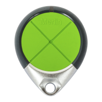
green – VAL (validate)
red – INC (increment)
blue – DEC (decrement)
yellow – FUN (function)
RJ-11 connector
to GT/SYSTEM
ground
+12-24 V dc/ac 10%
RS485:A to PC
RS485:B to PC
Antenna shield
Antenna