Merlin Power Systems version: 2.0.2
SmartGauge Installation and User Guide
Page 6
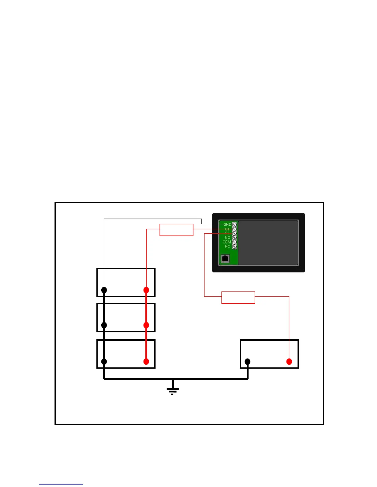
The SmartGauge does not require a separate shunt for installation. Battery voltage and state of
charge are both determined via sense wires connected directly to the terminals of one or both
battery banks. Referencing figure 2 below, to install:
1. An 18 gauge (AWG) ground wire from the GND terminal on back of the Smart-Gauge to the
battery negative post of the auxiliary battery bank.
2. An 18 gauge (AWG) positive sense wire from the B1 terminal on SmartGauge to the battery
positive post of the main battery bank. This wire must be fused at 3 amps with the fuse
holder installed as close to the battery as possible – note that the fuse should be outside any
battery compartment where battery gases may accumulate. It should not be run to busbars,
isolation switches, fuse panels etc.
3. If a second battery is to be monitored for voltage, run an additional 18 gauge (AWG) wire,
fused at 3 amps, from the B2 terminal on SmartGauge to the positive battery post of the
second battery bank or engine start bank. Again, this fuse should be located as close to the
battery as possible (but not inside the battery compartment if combustible gases can build
up).