96 Meru Access Point Installation Guide © 2010 Meru Networks, Inc.
Installing the Access Points
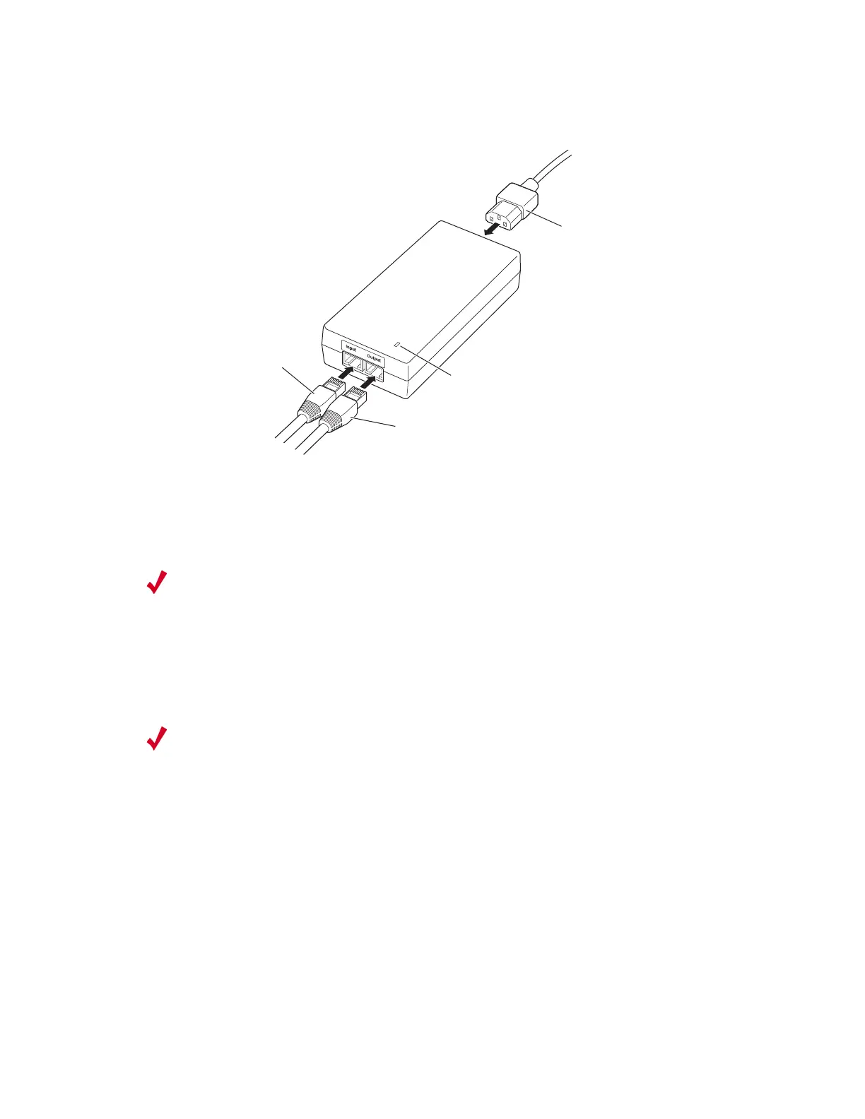
Figure 42: Connect OAP180 to Power Injector
2. Connect a straight-through unshielded twisted-pair (UTP) cable (not included)
from a local LAN switch to the RJ-45 port labeled Input on the power injector. See
the illustration above. Use Category 5e or better UTP cable for 10/100BASE-TX
connections.
3. Insert the power cable plug directly into the standard AC receptacle on the power
injector. See the illustration above.
4. Plug the other end of the power cable into a grounded, 3-pin socket, AC power
source.
5. Check the LED on top of the power injector to be sure that power is being supplied
to the OAP180 through the Ethernet connection.
Align Antenna
After the OAP180 unit is mounted, connected, and the radios are operating, the
antennas must be accurately aligned to ensure optimum performance of the OAP180
links. In this point-to-multipoint configuration all OAP180 nodes must be aligned
with the root OAP180 antenna.
AC power
Power LED indicator
Ethernet cable
from LAN switch
Ethernet cable to
wireless bridge
00206
Note:
The RJ-45 port on the power injector is an MDI port. If connecting directly to
a computer for testing the link, use a crossover cable.
Note:
For International use, you may need to change the AC line cord. You must use
a line cord set that has been approved for the receptacle type in your country.
 Loading...