IEC POWER INLET
This power inlet conforms to the IEC C-14 type standard, and is used with a cordset containing a matching
connector, and appropriate plug for the intended country’s AC requirements. The power supply is internally monitored by supervisory
protection circuits and thus contains a non-user replaceable fuse that opens in the event of a major failure. The amplifier is designed
to be used with grounded or earthed power, meaning that the chassis is always maintained at ground/earth potential even in the
event of a gross failure within (or external to) the amplifier. Never remove the grounding/earthing pin from the power plug, or alter
the power cable in any way.
COOLING FAN
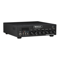
The SUBWAY D-800+ incorporates a low speed cooling fan to allow it to drive difficult loads (including 2 ohms)
at very high duty cycles. Be sure this fan inlet is not blocked or the amplifier’s protection circuits shutting the amplifier down due to
a thermal fault condition.
SPEAKER OUTPUTS
The SUBWAY D-800+ is rated to drive a minimum 2 ohm load (with the impedance selector switch set in
the 2 ohm position), meaning either 4 x 8 ohm cabinets or 2 x 4 ohm cabinets. The amplifier incorporates a pair of SpeakOn™ NL4FC
connectors wired in parallel that mate with either NL-2MP or NL4-MP plugs. Cables using NL-2 plugs contain only 1+/1- terminals
and will always be correctly wired for use with the amplifier, but cables using NL4 connectors come with different wiring configura-
tions. If using cables with NL-4 connectors, they may be constructed with standard 2 wire cable and they must be wired 1+ to 1+ and
1- to 1-. 4 wire cables are fine as well, terminals 2+ and 2- are not used. The cables to avoid are what are called NL4 bridge mode
cables, which are typically 2 wire, and wired 1+ to 1+ and 1- to 2+. These SHOULD be clearly marked but sometimes they are not,
so be aware of the possibility. Why SpeakOn™ cables and not the “old favorite” ¼” (or 6.35mm) connector? Well, there are a couple
important reasons, the first being that with the changes in safety laws globally, this amplifier requires “touch-proof connections” in
many markets because it exceeds the threshold for maximum voltage swing. The second reason is because the power amplifier’s
internal topology is BTL (bridge tied load), which means that neither terminals are at ground potential, so touch-proof connectors
provided an added layer of safety to the system.
SPEAKER IMPEDANCE
All speakers will have a “rated nominal impedance”. Impedance is resistance to AC electrical signal
flow which the power amplifier must deliver. The lower the impedance, the greater the current that the power amplifier must provide.
The lowest impedance that the amplifier is capable of driving safely is 2 ohms (with the impedance selector switch in the 2 ohm posi-
tion), which is a parallel connection (the standard connection of virtually all speaker cabinets) of either two x 4 ohm cabinets or four x
8 ohm cabinets. When operating the SUBWAY D-800+ into a nominal impedance load of 2.7 ohms (that’s one x 8 ohm cabinet + one
x 4 ohm cabinet or three x 8 ohm cabinets) the impedance selector switch should be set to the 2 ohm position. Note that measuring
speaker cabinets using an ohm meter will not give accurate results because ohm meters read DC resistance not AC impedance. AC
impedance will always be greater than the DC resistance, a typical 8 ohm speaker will usually measure between 5 and 7 ohms, a
typical 4 ohm speaker will usually measure between 2.5 and 3.5 ohms.
SPEAKER POLARITY (OR PHASE)
All speakers have “polarity”, that is a speaker wired to the industry standard will move
forward with a positive DC voltage applied to the positive terminal of the speaker and a negative voltage applied to the negative ter-
minal of the speaker. While there are standards, there are also deviations from standards, either by legacy (ie. early JBL drivers), by
faulty repair (incorrectly wired cabinet or defective recone parts) or a manufacturer choosing to ignore the standard. If a multi-driver
speaker cabinet or a pair of speaker cabinets does not appear to have the expected output or low end, it’s always a good idea to
double-check that all drivers move forward with positive DC voltage from a 9V battery applied to the + terminal (this will be the 1+
terminal on a SpeakOn™ connector, or the tip on a 1/4” connector). If you find on a multi-speaker cabinet that one speaker moves out
while the other does not move, it’s likely that the non-moving driver has failed or has become disconnected. If one driver moves out
while the other driver moves in, it’s likely that the driver moving in is wired incorrectly or in a sealed cabinet is failed or disconnected
and is merely being moved in the opposite direction by the air mass inside the cabinet itself. Being aware of these possibilities can
often help troubleshoot when something is not quite right.
IMPEDANCE SELECTOR SWITCH
The SUBWAY D-800+ is equipped with an impedance selector switch to match the
amplifier’s current drive capabilities to loads below 4 ohms. Whenever using loads of either 2.66 ohms (a 4 ohm load paralleled with
an 8 ohm load or three paralleled 8 ohm loads) or a 2 ohm load (a 4 ohm load paralleled with a 4 ohm load or four paralleled 8 ohm
loads) this switch must be set in the 2 ohm position. Failure to do so will result in the amplifier’s protection circuits shutting the ampli-
fier down due to an over-current fault condition.
PAGE 6
 Loading...