13
6 Electrical connection
7 Setting the hot-spot gradient
screw and remove the pressure ring. Push the pressure screw
and gasket over the temperature detector (9.5 mm diame-
ter) and the capillary tube. Thread the temperature detector
40 – 50 cm through the small cable gland connection until
it reaches the stop (at a depth of approx. 215 mm) in the
transformer temperature sensor sleeve of the ZT-F2.1 trans-
former temperature transmitter. Pull the capillary tube until
it is straight and then install it. Then tighten the cable gland
connection until it is liquid-tight.
Push the replacement sensor (Appendix/Fig. 7) into the tem-
perature sensor sleeve of the ZT-F2.1 transformer temperature
transmitter until it reaches the stop (at a depth of approx. 215
mm). Seal off the unused cable gland connection as tightly as
possible.
6 Electrical connection
6.1 Connecting the current transformer
Connect the current transformer to terminals 1 + 2 of the ZT-
F2.1 transformer temperature transmitter. The rated secondary
current should be 1.5 to 2 A. Use a ballast transformer accor-
ding the desired hot-spot gradient for other currents.
6.2 Pt100 measuring resistor
The ZT-F2.1 is equipped with a Pt100 measuring resistor con-
forming to IEC 751. The indicator instrument that is used can
be designed as 2, 3 or 4-conductor.
Length of the connection lines
The length of the connection lines depends on the specifica-
tions of the measuring transducer or indicator device to be
connected (e.g., one Pt-MU 100 Ω per line). In general, a line
length of 50 m should not be exceeded if the 3-conductor
technique is used. With the 3 or 4-conductor technique, make
sure that the individual leads are identical (i.e., same length,
same cross section). Otherwise differences may occur due to
incorrect compensation of the line resistors.
3-conductor technique
A 3-conductor indicator instrument (2 measuring lines and
1 compensation line) is to be used. The sensor lines are con-
nected to terminals 3 and 4 and the equalizing line to terminal
3a (see figure 3, item 2).
2-conductor technique
When a 2-conductor indicator instrument is used (2 measuring
lines), one measuring line is connected to terminal 3 and the
other measuring line is connected to terminal 4 (see figure 3,
item 2).
4-conductor technique
When a 4-conductor indicator instrument is used (2 measuring
lines and 2 compensation lines), the same connections are used
as for the 3-conductor technique. The second compensation
line must be connected to terminal 4
(see figure 3, item 2).
Option
When the configuration of the ZT-F2.1 with two Pt100 measu-
ring resistors is used, an additional indicator instrument can be
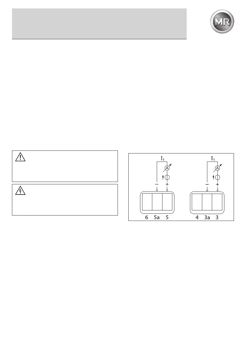
connected to terminals 6, 5a and 5 (see figure 3, item 3).
6.3 Option: Transducer 4...20mA
The ZT-F2.1 can be delivered with the 4...20 mA analog output
instead of the Pt100 measuring resistor. The 2-conductor
connection technique (R/L max. 750Ω at 24 V DC) is used with
connection to terminals 3a and 3 (see figure 2 and figure 3,
item 2).
Current loop I1 as passive analog output:
The device acts as a controlled resistance which, at a supply
voltage between 10-30 V DC, controls the current flow bet-
ween 4-20 mA as the measured temperature to be shown
Option
Optional configuration of the ZT-F2.1 with two analog outputs
or one analog output and one measuring resistor is also possi-
ble. Connection is then made to terminals 5a and 5 (see figure
2 and figure 3, item 3).
7 Setting the hot-spot gradient
7.1 Setting for 2 A CT nominal current
The hot-spot gradient (at nominal load) is set via the two DIP
switches S1 and S2 located on the ZT.F2.1 board. Determine
WARNING
Hazardous electrical voltages!
All connecting wiring must be free of voltage before opening
the device.
CAUTION
Electrical connections may only be carried out by qualified,
skilled personnel trained in the applicable safety regulati-
ons of the relevant country.
Fig. 2
min. 10 V DC
to max. 30 V DC
min. 10 V DC
to max. 30 V DC
 Loading...