15
12 Technical data
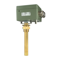
Dimensions: Refer to appendix, chap. 13.1
Materials:
Housing/terminal box: Aluminum alloy, die-casting,
RAL 7033, RAL 7038
Thread joint: Double thread G1B,
brass, blank
Installation: Thermometer pocket
DIN EN 50216-4 type A1
or similar
Protection mode: IP 56 acc. DIN EN 60 529
Flange: Teflon
Weight: 1.7 kg
Terminal box:
Cable glands: 1x M16 x 1.5 WADI;
2 x M25 x 1.5 WADI
Connection diagram: Refer to chap. 6
Connection terminals: 4 mm
2
single core
Ventilation: Via pressure compensation
element
Operating and ambient conditions:
CT nominal current: 2 A from current transformer
Overload stability: Continuously max. 3 A
(corresponds to 1.5 x
CT nominal current);
12 A for 30 sec.
Gradient adjustment: Via DIP switch (refer to chap. 7
and appendix chap. 13.2)
Measuring range thermometer: Depends on thermometer used
Ambient temperature: -50 to +85° C
Location: Indoors and outdoors,
tropical proof
Heating: Integrated in immersion tube
Power CT: P [VA] = I
2
CT
.
4.5 Ω
Mounting orientation: Any
Rated insulation voltage: 300 VAC, 50Hz
Analog output signal: Up to 2x for Pt100 / Pt1000
or up to 2x 4...20 mA,
others on request
Current output 4...20 mA:
Power supply: min. 10 V DC to max. 30 V DC
Load: max. 750 Ω for 24 V DC
If necessary, round off the calculated value to a whole number
since the value to be set from 4 K to 50 K can only be set in
1-K increments.
The setting can also be determined graphically with the follow-
ing diagram in figure 4 or figure 5.
If the intersection point of CT nominal current and target
temperature gradient is located between two of the pictured
curves, the required curve must be interpolated or the above
mentioned formula must be used to determine the value to
be set.
8 Checking the display
Allow the dial-type thermometer to warm up for 30 minutes
and then compare the readings on the dial and the electronic
display. The readings should be within the tolerance ranges of
both devices.
9 Service
Too high gradient display: Check if only oil is actually present
in the thermometer pocket.
Too low gradient display on mechanical thermometer: Check
if the mechanical temperature probe is inserted to the stop.
Check alternatively, whether there is enough oil inserted in the
thermometer pocket.
Deviations by special operating conditions can be corrected if
necessary by changing the DIP switches.
If the above instructions are not sufficient, please contact our
factory.
10 Maintenance
The ZT-F2.1 transformer is maintenance-free.
11 Overvoltage protection
All inputs and outputs are equipped with a safety circuit to
divert fault currents which can be created during lightning
strikes, switching events, or similar.
When a high voltage test > 300 V AC occurs between housing
and inputs or outputs, fault currents can be diverted which are
greater than the maximum permissible fault current.
8 Checking the display
9 Service
10 Maintenance
11 Overvoltage protection
12 Technical data
 Loading...