20
OPERATION BY STAND ALONE ID-TAG CONNECTION: Electrical connection suggestions
Fig. 5
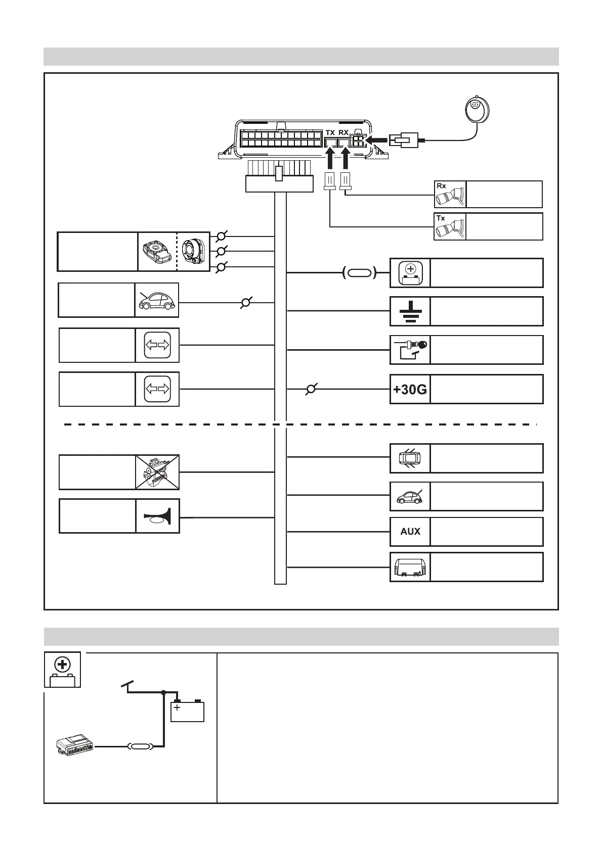
ELECTRICAL CONNECTIONS
Fig. 6
Connect the POSITIVE SUPPLY +30 by placing a 15A fuse or if possible
connecting on a protected line of the car.
Pay attention that in the chosen powering point the supply is present even
with the vehicle’s ignition panel is OFF for some time.
In the latest generation cars many power supplies points are below
control of an energy management system that “TURNING OFF” some
powering sources after the ignition panel is OFF for some time; The energy
management times and methods depending on the vehicle Brand and we
recommend following what is described in the MetaSystem application
technical data sheets.
PURPLE
LIGHT BLUE
(13)
(11)
(10)
SIREN
PRE-WIRING
( g. 26/27/28/29)
DIRECTION
INDICATORS
LIGHT BLUE/GREEN
DIRECTION
INDICATORS
ORANGE
BLACK
RED
POSITIVE
BATTERY (+30)
EARTH
IGNITION KEY
POSITIVE (+15)
SENSOR FOR
VOLUME
PROTECTION
(RED)
SENSOR FOR
VOLUME
PROTECTION
(BLACK)
MOUNT
15A FUSE
(6)
DARK BLUE
BROWN
GREEN
PURPLE
PINK
YELLOW
AUX CONNECTIONS
ENGINE
IMMOBILISATION
POSITIVE INPUT +30G
(CAR NETWORKENABLE)
DOOR
PROTECTION
BOOT
PROTECTION
POSITIVE COMMAND
AUXILIARY MODULES
POSITIVE ALARM
INPUT
NEGATIVE
COMMAND
HORN RELAY
PRE-WIRING
FOR BONNET
PROTECTION
( g.14)
(1)
(20)
(21)
(2)
(19)
(22)
(23)
(12)
(9)
(14)
(8)
(15)
RED
15A FUSE
 Loading...