ENGLISHen
16
See page 2.
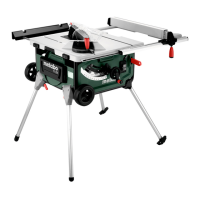
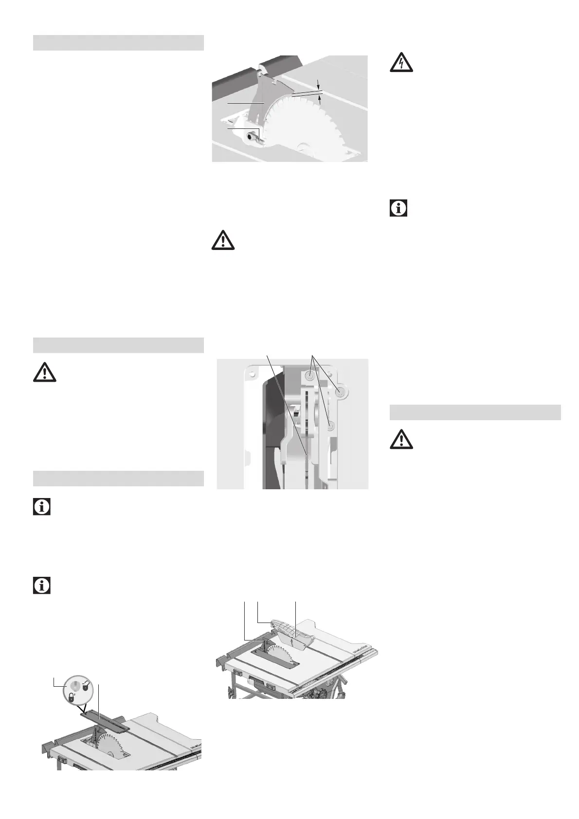
1Mitre fence
2 Clamping lever for securing the mitre fence
3 Table extension
4Table insert
5 Splitting wedge
6 Clamping lever for fastening the blade guard
7Blade guard
8Rip fence
9 Table extension
10 Knurled nut for fine setting of the parallel limit
stop
11 Clamping lever for securing the ripping fence
12 Push stick
13 Push stick holder
14 On switch
15 Off switch
16 Handwheel for adjusting the angle of
inclination
17 Crank for adjusting cutting depth
18 Clamping lever to lock the angle of inclination
19 Bevel limitation stop
20 Adjustable foot (to balance uneven floors)
21 Adjustment screw (clamping of the ripping
fence)
22 Blade guard holder
23 Mitre fence holder
24 Cable winder
25 Extractor connection piece
26 Ripping fence holder
27 Open end wrench
28 Toolholder
Ensure firm footing and keep your
balance at all times.
1. Lift tool with two persons out of packaging.
2. Place saw down on stable table or work
bench.
3. Even out irregularities in the floor using the
adjustable foot (20): Undo the screw, adjust
the foot, tighten the screw up firmly.
4. Bolt saw firmly onto table or work bench.
Note:
Rubber chips might fly around during initial
commissioning. This depends on the design and
is harmless.
7.1 Assembly
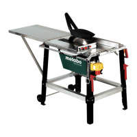
Adjust splitting wedge (if required)
Note:
The splitting wedge (5) has been correctly set at
the factory. Readjustment prior to initial operation
is only required should the splitting wedge have
become maladjusted in transit.
1. Raise saw blade fully.
2. Turn screw (29) anti-clockwise, lift table insert
(4) and remove.
3. Release locking lever (30) (turn anti-
clockwise!).
4. Pull the splitting wedge (5) out of the lower
transport position upwards as far as the stop.
5. Checking the splitting wedge:
– The distance between the saw blade's outer
edge and the splitting wedge needs to be
3to8mm.
– The splitting wedge must be in alignment with
the saw blade.
Danger!
The splitting wedge is one of the safety
devices and must be correctly installed for
safe operation.
6. Tighten locking lever (30) (turn clockwise!).
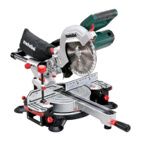
Set lateral alignment (if required):
Splitting wedge (5) and saw blade must be in true
alignment.
7. Release the three Allen screws (31).
8. Align the splitting wedge (5) flush with the saw
blade.
9. Tighten the three Allen screws (31).
10.Fasten table insert (4) and lock with screw
(29).
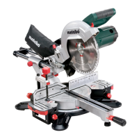
Blade guard installation
1. Raise saw blade fully.
2. Install the blade guard (7) at the splitting
wedge (5).
3. Firmly tighten the blade guard with the lock
lever (6).
Height adjustment of the table insert
(if necessary)
The table insert (4) is set correctly when its
surface is 0 mm to 0.7 mm below the table
surface.
Adjust the 4 screws in the corners of the table
insert (4) to adjust the height.
7.2 Connection to Power Mains
Danger! High voltage
• Operate the device in dry surroundings
only.
• Operate machine only on a power source
meeting the following requirements (see
also “Technical Specifications”):
– outlets properly installed, earthed and
tested;
– mains voltage and system frequency
conform to the voltage and frequency
shown on the machine´s rating label;
– Fuse protection by a residual current
circuit breaker (RCCB) of 30 mA sensi-
tivity;
Note:
Check with your local Electricity Board or
your electrician if in doubt whether your
house service connection meets the
requirements.
• Make sure the power supply cable is out of
the way, so that it does not interfere with
the work and does not pose a tripping
hazard or will get damaged.
• Protect the power supply cable from heat,
aggressive liquids and sharp edges.
• Use only rubber-jacketed extension cables
with sufficient lead cross-section.
• When working out of doors, only use
extension cables that are also approved for
outdoors.
• Do not pull on the power supply cable to
unplug.
• Avoid accidental start-up: ensure that the
on/off switch is switched off when inserting
the plug in the socket.
Risk of injury!
This saw may only be operated by one
person at a time. Other persons shall stay
only at a distance to the saw for the purpose
of feeding or removing stock.
Before starting work, check to see that the
following are in proper working order:
– power cable and plug
– ON/OFF switch
– Splitting wedge
– Blade guard
– feeding aids (push stick, push block and
handle).
Use personal protection gear:
–dust respirator;
– ear protection;
– safety goggles.
Assume proper operating position:
– at the front of the saw;
– in front of the saw;
– to the left of the line of cut;
– when working with two persons, the other
person must remain at an adequate dis-
tance to the saw.
If the type of work requires, use the follow-
ing:
– suitable workpiece supports – if other-
wise workpiece would fall off the table af-
ter cutting;
– dust collector.
Avoid typical operator mistakes:
– Do not attempt to stop the saw blade by
pushing the workpiece against its side.
Risk of kickback.
– Always hold the workpiece down on the
table and do not jam it. Risk of kickback.
5. Overview
6. Installation
7. Initial Operation
8. Operation
 Loading...