2
1
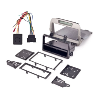
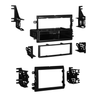
ALL VEHICLES
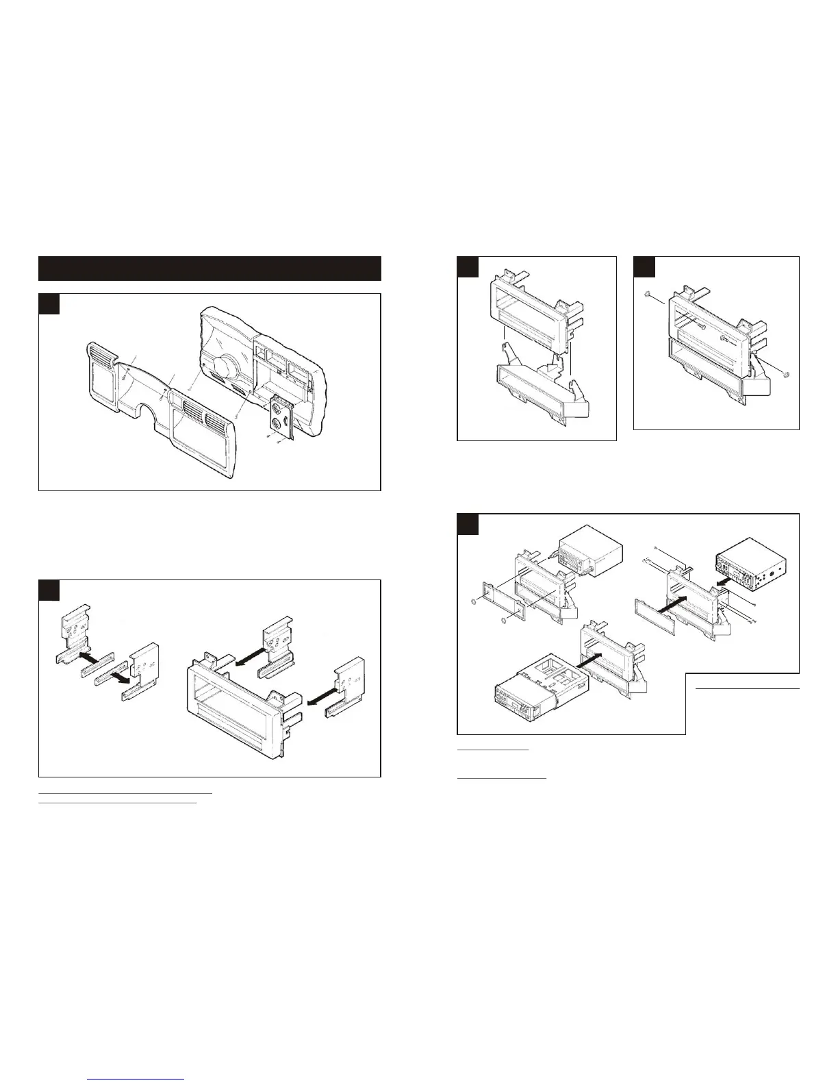
Disconnect the negative battery terminal to prevent an accidental short circuit. Remove (2)
screws above the speedometer cluster. Remove the ashtray and (1) screw exposed in the
ashtray cavity. Remove (2) screws from the lower steering column trim bezel and remove the
bezel. Unclip the dash trim bezel, disconnect the light switch wiring and remove the bezel.
Remove (4) screws securing the climate control panel and remove the panel. Remove (4)
screws securing the factory head unit/pocket assembly and disconnect the wiring.
1
2
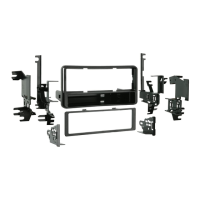
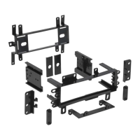
IF AN EQUALIZER WILL NOT BE INCLUDED: Skip to step #3.
IF AN EQUALIZER WILL BE INCLUDED: Snap the Equalizer Spacers onto the bottom of
the ISO-DIN Brackets. (see Fig. A). Slide the Brackets onto the Radio Housing legs. (see
Fig. B)
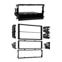
DIN HEAD UNITS: Slide the DIN cage into the kit and secure by bending the metal locking
tabs down. Slide the aftermarket head unit into the cage until secure. (see Fig. B)
ISO-DIN HEAD UNITS: Cut and remove the shaft supports from the Faceplate. Snap the
Faceplate into the Radio Housing. Slide the aftermarket head unit into the back of the kit.
Slide the ISO-DIN Brackets onto the Housing legs and align the holes in the Brackets with the
holes in the unit. Mount the Brackets to the unit with (4) 5mm Flat-head Screws supplied
("A"). Mount the Brackets to the top of the Housing legs with (2) #6 Self-tapping Screws
("B"). (see Fig. C)
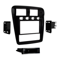
2-SHAFT HEAD UNITS:
Snap the Faceplate into the
Radio Housing. Slide the
aftermarket head unit into
the kit and secure with shaft
nuts. (see Fig. A)
5
Fig. A
3
Remove the pocket from the factory head
unit and slide the mounting tabs on the
pocket over the side tabs on the Radio
Housing.
4
Mount the pocket to the Radio Housing with
(2) Carriage Bolts and (2) Nuts supplied.
Fig. B
Fig. B
Fig. A
Fig. C
"B"
"B"
"A"
"A"