SWC-01
1
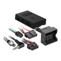
Wiring The SWC-01
Red (+) wire: connect this wire to a fused 12 volt accessory wire
Black (-) wire: connect this wire to the vehicles chassis ground
Green wire: steering wheel control wire for resistive type systems (see applications)
Pink wire: steering wheel control wire for Data type systems (see applications)
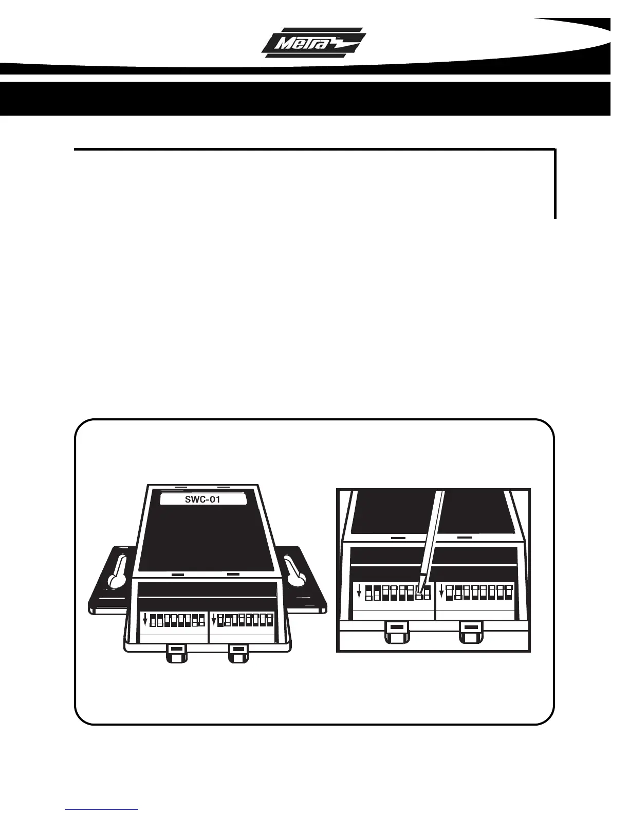
Radio DIP Switch Settings
If you look at the DIP switches on SWC-01 you will see that they are separated into 2
groups of 8 DIP
switches each. One side is labeled RADIO and the other side is
labeled CAR. The chart below will show the DIP switch settings for the RADIO side.
The CAR side will be listed with each individual vehicle inside this manual.
ON
ON
CAR
RADIO
1 2 3 4 5 6 7 8 1 2 3 4 5 6 7 8
ON
ON
CAR
RADIO
1 2 3 4 5 6 7 8 1 2 3 4 5 6 7 8
Refer to Vehicle Chart to select the proper dip switch position and move
switch "up" or "down" with a small screwdriver to select vehicle model,
radio brand, and external CD changer or external tuner/XM if present.
Example above represents a Chevrolet Suburban 2004-2005 with Sony radio
and no external CD changer or external tuner/XM present.
• * Note: Do NOT plug in wiring harness into the SWC-01 until all DIP switch settings are set.