A 1532 EVSE adapter A 1532 operation
8
4 A 1532 operation
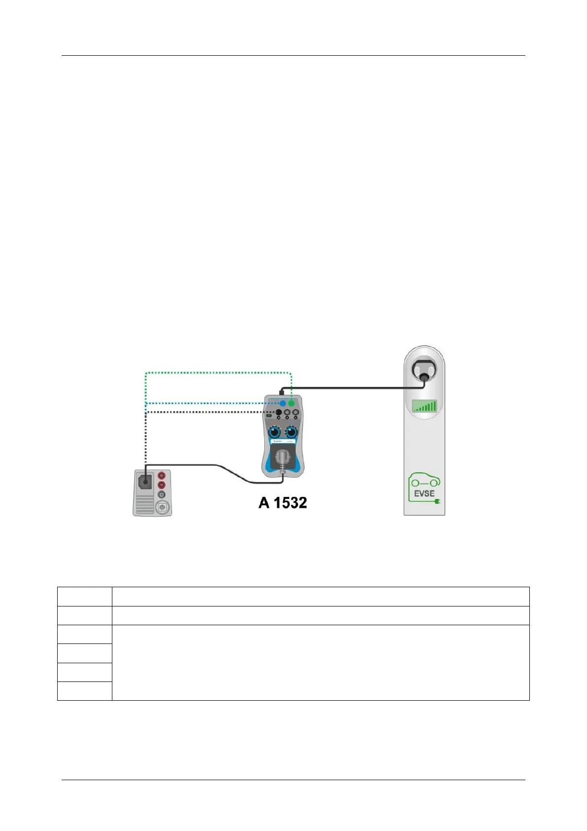
Testing procedure:
Connect the A 1532 output to the installation tester (via mains test socket or via safety
banana sockets)
Set PP STATE (3) to position N.C. and CP STATE (4) to position A.
Connect A 1532 plug (6) to the EVSE.
Run installation tests for non-energized installation circuits.
Simulate different charging conditions with PP STATE (3) and CP STATE (4). Verify the
response of the EVSE.
In PP STATE (3) position different to N.C. and CP STATE (4) position in C or D, the
EVSE output is energized (indicated by one or more (2) Voltage on EVSE indicators).
Run installation tests for energized installation circuits.
Set CP STATE (4) to position A to de-energize EVSE, before disconnecting A 1532 plug
(6) from EVSE.
Note:
Only phase L1 of 3-phase EVSE is accessible through test socket (5).
Figure 4.2: A 1532 connection
PP STATE options
Error condition or disconnection of plug
Coding for maximum current of the EV cable.
EVSE is connected and can operate in any of these coding position.