A 1532 EVSE adapter A 1532 operation
9
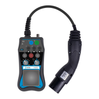
CP STATE options
EVSE in idle state, EV not ready to receive energy,
EVSE does not supply energy
EV detected, EV not ready to receive energy, EVSE does
not supply energy
EV charged without
ventilation
EV ready to receive energy, EVSE is supplying energy if
ventilation is not required.
EV charged with
ventilation
EV ready to receive energy and requires ventilation,
EVSE is supplying energy only if ventilation exists.
EVSE doesn’t supply energy (no power).
The EV supply equipment unlocks the socket outlet at
maximum of 30 s.
Recommended sequences:
A-B-C for non-ventilated charging
A-B-D for charging with ventilation required
E is required for simulating Pilot failure.
Note:
With A1532 alone only proximity pilot and control pilot functions of EVSE can be
checked.
Checking CP signal
Connect Oscilloscope to BNC connector (7) using 10:1 probe with 10 MΩ input
resistance.
Set PP STATE (3) position to proper EVSE current output selection.
Set CP STATE (4) to position A.
Set tested EVSE to operate.
Set CP STATE (4) to position B and/or C and modify PP STATE (3) position to all
applicable currents.
Check waveforms and amplitudes of measured CP signal.
Notes:
If the input resistance is 1 MΩ instead of recommended 10 MΩ, the measured signal
amplitude is approx. 17 % lower than actual value.
Oscilloscope probe shall be compensated to get proper frequency response.
Portable / handheld battery powered oscilloscope is recommended for observing CP
signal.
Warning:
If 50 Hz / 60 Hz noise is visible in the signal, it is possible to suppress it by connecting
the PE socket to oscilloscope ground. However in this case it must be assured before
that there is no hazardous voltage on the PE conductor of the EVSE and use of safe
accessories is recommended.