Do you have a question about the METREL EurotestXE MI 3102H and is the answer not in the manual?
General warnings and notes for safe use of the instrument.
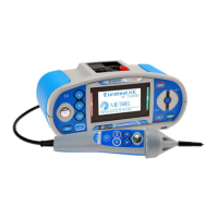
Detailed description of the instrument's front panel controls and display.
Identification and function of the instrument's various connectors.
Description of the back panel components including battery and fuse compartments.
Details found on the bottom of the instrument, including labels and openings.
Instructions and examples for carrying the instrument using the provided accessories.
List of standard and optional accessories included with the instrument.
Explanation of symbols, messages, and the instrument's display layout.
How the instrument displays voltage and terminal status during measurements.
Understanding the battery level and charging indicators on the display.
Explains various warning and message icons that appear during measurements.
How to interpret the results displayed in the result field (Pass, Fail, Abort).
Explains other miscellaneous messages that can be displayed by the instrument.
Explains the different sound signals emitted by the instrument.
Description of the function and parameter line on the instrument's display.
How to choose different measurement functions and sub-functions using the selector switch.
How to adjust measurement parameters and set limit values for tests.
How to access and use the instrument's built-in help menus with connection diagrams.
Accessing and configuring instrument settings like language, ports, and commanders.
Adjusting the scaling factor for prospective short/fault current calculations.
How to select the desired language for the instrument's interface.
Setting up RS232 or USB communication ports for data transfer.
Enabling or disabling support for remote commanders attached to the instrument.
Restoring the instrument's parameters and settings to their original factory values.
How to adjust the backlight level and contrast of the instrument's display.
Procedures and safety precautions for measuring insulation resistance.
Step-by-step guide on how to perform insulation resistance tests.
Performing Dielectric Absorption Ratio (DAR) and Polarization Index (PI) tests.
Methods for testing electrical continuity and low resistance.
How to measure low resistance values, ensuring safety and proper connections.
Performing standard continuity tests using the instrument.
Comprehensive guide to testing Residual Current Devices (RCDs).
How to set the limit for permissible contact voltage during RCD tests.
Selecting the rated trip-out current for RCD testing.
Selecting RCD type (G/S) and test current starting polarity for RCD tests.
Measuring voltage on accessible parts connected to the PE terminal.
Verifying the effectiveness of RCDs by measuring trip-out times.
Measuring the current at which the RCD trips.
Performing a complete RCD test sequence automatically.
Measuring fault loop impedance and calculating prospective fault current.
Procedure for measuring fault loop impedance using high test current.
Measuring fault loop impedance while avoiding RCD trip-out.
Measuring line impedance and calculating prospective short-circuit current.
Testing the phase rotation of three-phase systems to prevent damage.
Measuring voltage and frequency of mains power supply.
Measuring the resistance of earthing systems using a 3-wire method.
Measuring AC currents using a current clamp.
Performing illumination measurements using a Luxmeter sensor.
Checking for phase voltage at the PE terminal to detect dangerous wiring errors.
Steps and options for saving measurement data to the instrument's memory.
How to access and view previously saved measurement data.
Procedures for deleting individual results or all stored data.
Overview of the PC software for data management and reporting.
Instructions on how to safely replace the instrument's fuses.
Recommendations for cleaning the instrument's exterior.
Importance and procedure for regular calibration to ensure accuracy.
Information on obtaining service and repairs for the instrument.
Technical details for insulation resistance measurements, including ranges and accuracies.
Technical details for continuity and low resistance measurements.
Technical data for RCD testing, including current, time, and voltage parameters.
Technical details for fault loop impedance and prospective fault current measurements.
Technical details for line impedance and prospective short-circuit current measurements.
Technical specifications for measuring resistance to earth.
Technical data for true RMS current measurements.
Technical details for illumination measurements using Luxmeter sensors.
Technical data for phase sequence testing.
Technical details for voltage and frequency measurements.
Technical data for the online voltage monitoring feature.
Overall specifications including power, dimensions, and operating conditions.
Comprehensive list of fuse parameters for various types and ratings.
| Category | Measuring Instruments |
|---|---|
| Insulation Resistance Range | 0.01 MΩ to 10 GΩ |
| DC Voltage | 0 V to 1000 V |
| AC Voltage | 0 V to 1000 V |
| Voltage Range | 0 V to 1000 V |
| Phase Sequence | Yes |
| Power Supply | Rechargeable battery |
| Battery Type | Li-ion |
| Communication Interface | USB, Bluetooth |
| Bluetooth | Yes |
| Weight | 1.5 kg |
| Operating Temperature | -10 °C to +50 °C |
| Storage Temperature | -20 °C to +60 °C |
| Protection Class | IP 54 |
| Type | Multifunction Installation Tester |
| Measurement Functions | Insulation Resistance, Loop Impedance, RCD Testing, Earth Resistance, Voltage, Frequency, Phase Sequence |
| Test Voltage | 250 V, 500 V, 1000 V |
| RCD Testing | Type AC, A, B, F |
| Frequency Range | 45 Hz to 65 Hz |
| Display | LCD with backlight |