Do you have a question about the METREL MI 3125 and is the answer not in the manual?
Safety warnings for instrument use, electrical installations, and handling.
Specific warnings for Insulation resistance, continuity, PE terminal, and socket tests.
Warnings for continuity, RCD, Z-LOOP, Z-LINE, and Socket tests.
Procedure to improve battery lifetime for new or long-unused cells.
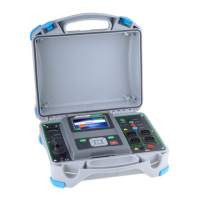
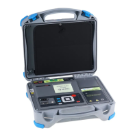
Description of the instrument's front panel layout, buttons, and LCD display.
Details of the instrument's input/output connectors and their functions.
Description of the instrument's back panel, including battery compartment and fuse.
Explanation of the instrument's display elements like result, message, and voltage fields.
Explanation of result field indicators (PASS/FAIL) and sound warnings.
Instructions on how to adjust the display's backlight and contrast settings.
Lists standard and optional accessories included with the instrument.
How to select different test or measurement functions using the function selector.
Guide for selecting the instrument's display language.
How to restore the instrument's settings to default factory values.
How to select the relevant standard for RCD test procedures.
Setting the Isc factor and enabling/disabling commander support.
Further notes on commander support settings and potential interference.
Procedure to compensate for test lead resistance for accurate measurements.
How to measure voltage, frequency, and determine phase sequence.
Steps for performing voltage measurements and interpreting results in single/three-phase systems.
How to perform insulation resistance tests and typical applications.
Step-by-step guide for insulation resistance measurement and result interpretation.
How to measure earth connection and equipotential bonding resistance.
Procedure for performing the 200mA resistance measurement.
Overview of RCD testing parameters, types, and standards.
Procedure for measuring contact voltage (Uc) to verify RCD safety.
How to measure the trip-out time of an RCD at different residual currents.
Procedure to measure the trip-out current of an RCD.
How to perform a complete, automated RCD test sequence.
Examples of individual steps and overall results in RCD autotest.
Explanation of displayed results and important notes for RCD autotest.
How to measure fault loop impedance and calculate prospective fault current.
Steps for performing fault loop impedance measurements and calculation of Isc.
How to measure line impedance and calculate prospective short-circuit current.
Steps for performing line impedance measurements and calculation of Isc.
How to perform a socket outlet test for polarity and connection checks.
Steps for executing the socket outlet test and interpreting its results.
How the PE test terminal detects dangerous voltages on PE wire due to incorrect wiring.
Steps for performing the PE terminal test and related operational notes.
Instructions for replacing the instrument's fuse, including warnings.
Instructions for cleaning the instrument's housing.
Importance and procedure for regular instrument calibration.
How to upgrade the instrument's software via PC.
Information on how to contact for repairs and service.
Technical details for insulation resistance measurements.
Technical specifications for continuity and low resistance measurements.
RCD testing general data, test current shapes, and contact voltage specs.
Technical specs for RCD trip-out time and trip-out current measurements.
Technical specifications for fault loop impedance measurements.
Specs for prospective fault current and RCD selected fault loop impedance.
Technical specifications for line impedance and prospective short-circuit current.
Specs for socket test, phase rotation, voltage, and frequency measurements.
Specs for online voltage monitor, general data, operating, and storage conditions.
Tables showing disconnection times and prospective short-circuit currents for NV and gG fuses.
Tables for disconnection times and prospective short-circuit currents for B and C fuses.
Tables for disconnection times and prospective short-circuit currents for K and D fuses.
Lists suitable accessories for various measurement functions.
| Type | Multifunction Installation Tester |
|---|---|
| Insulation Resistance | Yes |
| Continuity Test | Yes |
| Loop Impedance | Yes |
| RCD Testing | Yes |
| Voltage Measurement | Yes |
| Frequency Measurement | Yes |
| Display | LCD |
| Power Supply | 6 x 1.5 V AA batteries |
| Loop Resistance Resolution | 0.01 Ω |
| Frequency | 45 - 65 Hz |
| Line Voltage Resolution | 1 V |
| Insulation Resistance Test Voltage | 50 V, 100 V, 250 V, 500 V, 1000 V |
| Insulation Resistance Resolution | 0.01 MΩ |
| Continuity Resistance Resolution | 0.01 Ω |
| Test Current | 200 mA |
| DC Voltage | Up to 600 V |
| Loop Resistance | 0.0 Ω - 1999 Ω |
| Line Voltage | Up to 550 V |
| Line Voltage Accuracy | ±2% ±2 digits |
| Rated Residual Current | 10 mA, 30 mA, 100 mA, 300 mA, 500 mA |
| Insulation Resistance Range | 0.01 MΩ to 1 TΩ |
| Continuity Resistance | 0.0 Ω - 1999 Ω |
| Dimensions | 220 x 103 x 55 mm |
| Operating Temperature | -10°C to 50°C |
| Storage Temperature | -20°C to +60°C |
| Safety Standards | EN 61557 |
| Loop Resistance Accuracy | ±(5% + 3 digits) |