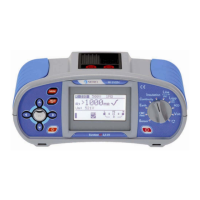
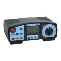
MI 3125 InstaltestCOMBO Table of contents
3
Table of contents
1 Preface ....................................................................................................................5
2 Safety and operational considerations.................................................................6
2.1 Warnings and notes ..........................................................................................6
2.2 Battery and charging .........................................................................................9
2.2.1 New battery cells or cells unused for a longer period ......................................... 10
2.3 Standards applied ...........................................................................................11
3 Instrument description.........................................................................................12
3.1 Front panel ......................................................................................................12
3.2 Connector panel ..............................................................................................13
3.3 Back side.........................................................................................................14
3.4 Display organization ........................................................................................15
3.4.1 Terminal voltage monitor..................................................................................... 15
3.4.2 Battery indication................................................................................................. 15
3.4.3 Message field ......................................................................................................15
3.4.4 Result field .......................................................................................................... 16
3.4.5 Sound warnings .................................................................................................. 16
3.4.6 Help screens ....................................................................................................... 16
3.4.7 Backlight and contrast adjustments .................................................................... 17
3.5 Instrument set and accessories.......................................................................18
3.5.1 Standard set MI 3125.......................................................................................... 18
3.5.2 Optional accessories........................................................................................... 18
4 Instrument operation............................................................................................19
4.1 Function selection ...........................................................................................19
4.2 Settings ...........................................................................................................20
4.2.1 Language ............................................................................................................ 20
4.2.2 Initial settings ...................................................................................................... 21
4.2.3 RCD standard ..................................................................................................... 22
4.2.4 Isc factor.............................................................................................................. 23
4.2.5 Commander support ........................................................................................... 23
5 Measurements ......................................................................................................25
5.1 Compensation of test leads resistance............................................................25
5.2 Voltage, frequency and phase sequence ........................................................
26
5.3 Insulation resistance........................................................................................
28
5.4 Resistance of earth connection and equipotential bonding .............................30
5.4.1 R LOWΩ, 200 mA resistance measurement....................................................... 31
5.5 Testing RCDs ..................................................................................................32
5.5.1 Contact voltage (RCD Uc)................................................................................... 33
5.5.2 Trip-out time (RCDt)............................................................................................ 34
5.5.3 Trip-out current (RCD I) ...................................................................................... 35
5.5.4 RCD Autotest ...................................................................................................... 36
5.6 Fault loop impedance and prospective fault current ........................................39
5.7 Line impedance and prospective short-circuit current .....................................41
5.8 Socket outlet test.............................................................................................
43
5.9 PE test terminal ...............................................................................................
45
 Loading...

