MI 3125 InstaltestCOMBO Display organization
15
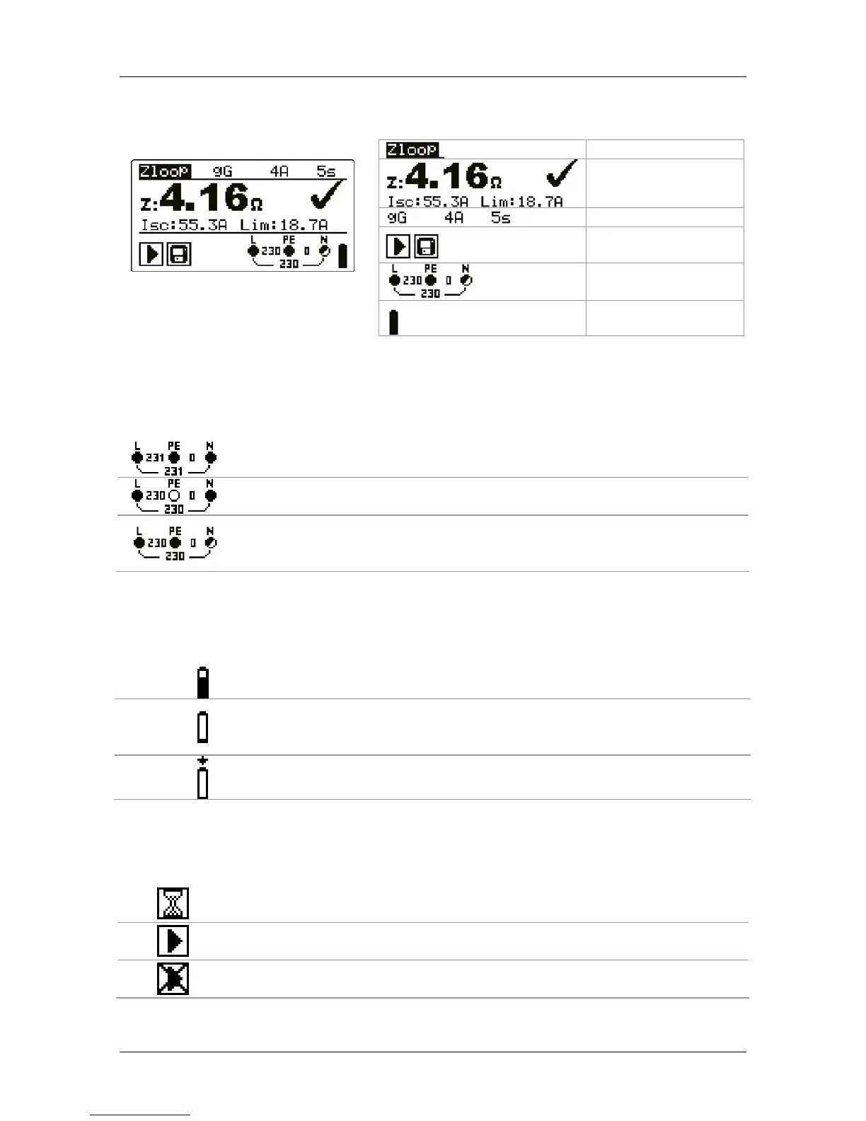
3.4 Display organization
Figure 3.5: Typical function
display
Function name
Result field
Test parameter field
Message field
Terminal voltage
monitor
Battery indication
3.4.1 Terminal voltage monitor
The terminal voltage monitor displays on-line the voltages on the test terminals and
information about active test terminals.
Online voltages are displayed together with test terminal indication. All
three test terminals are used for selected measurement.
Online voltages are displayed together with test terminal indication. L
and N test terminals are used for selected measurement.
L and PE are active test terminals; N terminal should also be connected
for correct input voltage condition.
3.4.2 Battery indication
The indication indicates the charge condition of battery and connection of external
charger .
Battery capacity indication.
Low battery.
Battery is too weak to guarantee correct result. Replace or
recharge the battery cells.
Recharging in progress (if power supply adapter is connected).
3.4.3 Message field
In the message field warnings and messages are displayed.
Measurement is running, consider displayed warnings.
Conditions on the input terminals allow starting the measurement;
consider other displayed warnings and messages.
Conditions on the input terminals do not allow starting the
measurement, consider displayed warnings and messages.

 Loading...