Do you have a question about the METREL MI 3115 PV and is the answer not in the manual?
General warnings and safety notes for instrument operation and measurements.
List of standards the instrument is manufactured and tested according to.
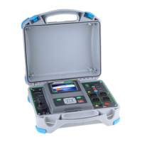
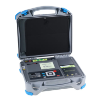
Details of the items included in the standard package of the instrument.
Information on optional accessories available for the instrument.
Identification and description of the instrument's front panel components.
Explanation of the functions of the instrument's physical keys.
Description of how to use touch gestures for instrument navigation.
Details on using the virtual keyboard for text input on the instrument.
Explanation of safety checks, symbols, and warning messages displayed by the instrument.
Overview of the two modes for selecting single tests on the instrument.
Description of results, statuses, and information displayed during single tests.
Details on visual inspection tests, including item checks and status application.
Information on measuring and synchronizing environmental data with the instrument.
Descriptions of various single test measurements like Visual Inspection and R low.
How to select, search, and organize Auto Sequences on the instrument.
Steps for carrying out Auto Sequences, including pre-programmed tests and results.
Importance and recommendation for regular calibration of the instrument.
Information on how to handle repairs and service for the instrument.
Instructions on how to clean the instrument safely and effectively.
Steps to establish USB or RS232 communication with a PC.
How to communicate with the PV Remote WL device via Wi-Fi.
Detailed technical specifications for various tests and measurements performed by the instrument.
Information about the Metrel ES Manager software for instrument control.
Details on using the Black Box protocol for instrument control via PC.
Information about the Software Development Kit for interfacing with the instrument.
Explanation of structure elements like Node, Object, Inverter, etc. in Memory Organizer.
Specific notes related to instrument profiles.
Explanation of how to calculate PV measurements to Standard Test Conditions (STC).
| Polarity Test | Yes |
|---|---|
| Data Logging | Yes |
| DC Voltage Measurement Range | 0 to 1000 V |
| Insulation Resistance Measurement Voltage | 250 V, 500 V, 1000 V |
| Continuity Measurement Current | > 200 mA |
| Uoc Measurement Range | 0 to 1000 V |
| PV Module Temperature Measurement Range | -20 °C |
| RCD Test | Yes |
| Communication | USB, Bluetooth |
| Display | LCD with backlight |
| Power Supply | Rechargeable battery |
| Safety Standards | EN 61010-1 |
| Safety Standard | IEC 61010-1 |
| Measurement Functions | PV system testing, insulation resistance, continuity, RCD, earth resistance, voltage, current |
| DC Current Measurement Range | 0 to 20 A |
| AC Current Measurement Range | 0 to 20 A |
| Isc Measurement Range | 0 to 20 A |