Do you have a question about the METREL EurotestCOMBO MI 3125 and is the answer not in the manual?
General warnings and safety precautions for instrument operation.
Details on instrument power supply, battery types, and charging procedures.
Lists the regulations and standards the instrument complies with.
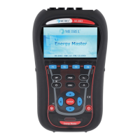
Description and identification of controls and indicators on the instrument's front.
Details and location of input/output connectors on the instrument.
Description of the instrument's rear panel features and components.
Explanation of the instrument's LCD display layout and elements.
Lists the standard and optional accessories included with the instrument.
Guide on how to select different measurement and test functions.
Instructions for configuring instrument options like language and parameters.
Procedure for measuring voltage, frequency, and phase sequence.
Method for performing insulation resistance tests for safety.
Procedure for measuring earth connection and bonding resistance.
Detailed steps for testing Residual Current Devices (RCDs).
Measuring fault loop impedance and calculating prospective fault current.
Measuring line impedance and voltage drop.
Procedure for measuring earth resistance for protective measures.
Procedure for testing the protective earth conductor for faults.
Overview of how measurement results are stored in instrument memory.
Description of the instrument's memory organization and data storage levels.
Instructions on how to save completed test results to memory.
Guide on how to retrieve stored measurement results from memory.
Procedures for deleting stored measurement data from the instrument.
Information on transferring data via USB, RS232, and Bluetooth.
Instructions on how to safely replace the instrument's fuse.
Guidelines for cleaning the instrument's housing and surfaces.
Information on the importance and procedure for periodic instrument calibration.
Information on how to obtain service or repairs for the instrument.
Technical specifications for insulation resistance measurements.
Technical specifications for continuity and resistance measurements.
Technical specifications related to RCD testing functions.
Technical specifications for fault loop impedance and prospective fault current.
Technical specifications for line impedance and voltage drop measurements.
Technical specifications for earth resistance measurements.
Technical specifications for voltage, frequency, and phase rotation measurements.
General technical data, operating conditions, and dimensions of the instrument.
Table of prospective short-circuit current for various fuse types.
Table of fuse impedances for 230V AC systems according to AS/NZS 3017.
List of applied modifications for specific country requirements.
Details on specific modifications related to country requirements.
List of standard references relevant to IT supply systems.
Basic principles and characteristics of IT supply systems.
Guides and procedures for performing measurements in IT systems.
Safety warnings and precautions for using commanders.
Information on battery types and usage for commanders.
Description and identification of commander components and features.
Instructions on how to operate the commanders.
| Brand | METREL |
|---|---|
| Model | EurotestCOMBO MI 3125 |
| Category | Measuring Instruments |
| Language | English |