MI 3125 / BT EurotestCOMBO Measurements
36
Displayed result:
R............Resistance
Notes:
Continuous buzzer sound indicates that measured resistance PASS the limit.
There is no sound if the limit is disabled (---).
5.3.3 Compensation of test leads resistance
This chapter describes how to compensate the test leads resistance in both continuity
functions, R LOWΩ and CONTINUITY. Compensation is required to eliminate the
influence of test leads resistance and the internal resistances of the instrument on the
measured resistance. The lead compensation is therefore a very important feature to
obtain correct result.
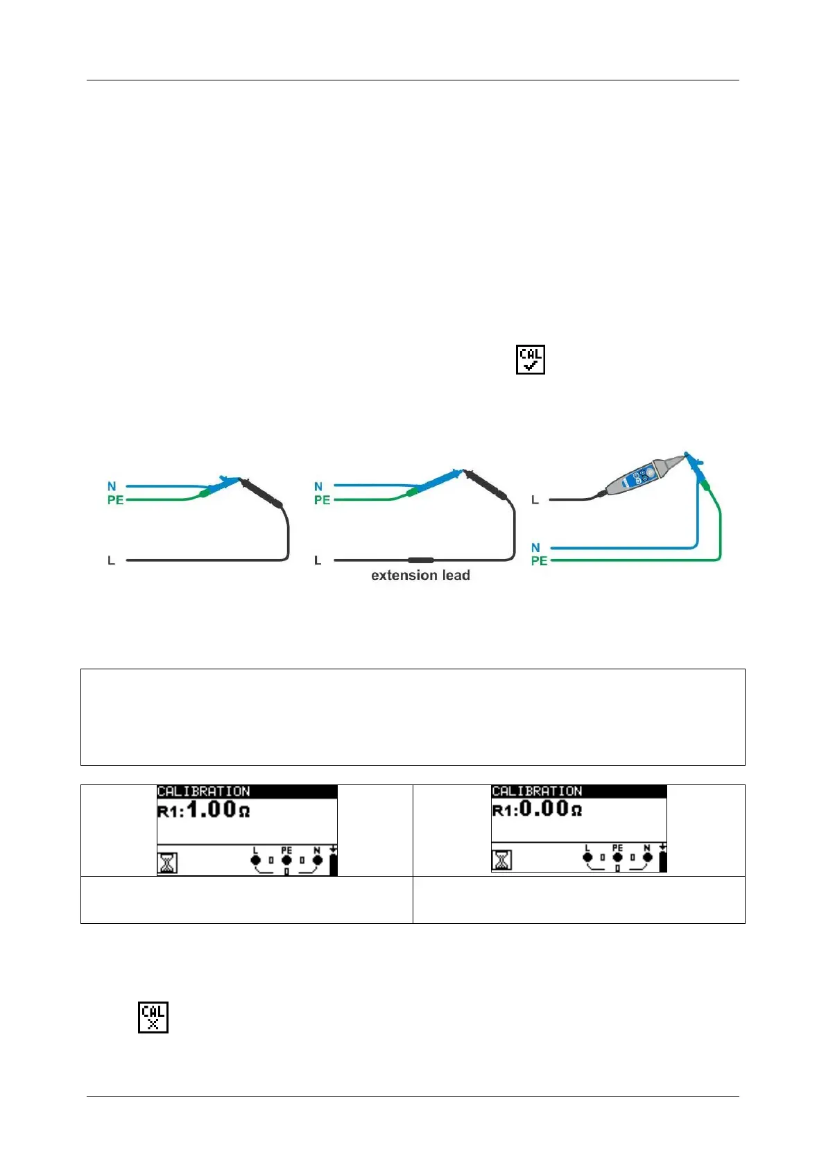
R LOWΩ and CONTINUITY has common compensation. symbol is displayed if the
compensation was carried out successfully.
Circuits for compensating the resistance of test leads
Figure 5.13: Shorted test leads
Compensation of test leads resistance procedure
Select R LOWΩ or CONTINUITY function.
Connect test cable to the instrument and short the test leads together (see figure
5.13).
Press TEST to perform resistance measurement.
Press the CAL key to compensate leads resistance.
Figure 5.14: Results with old calibration
values
Figure 5.15: Results with new calibration
values
Note:
The highest value for lead compensation is 5 . If the resistance is higher the
compensation value is set back to default value.
is displayed if no calibration value is stored.

 Loading...