MI 3125 / BT EurotestCOMBO Measurements
34
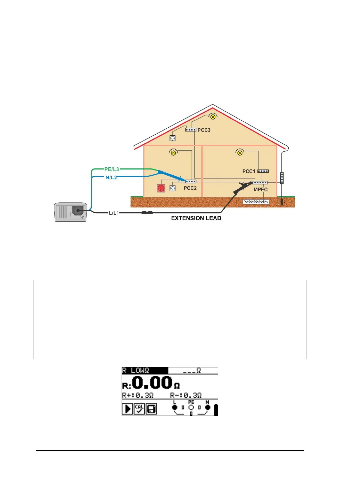
5.3.1 R LOWΩ, 200 mA resistance measurement
The resistance measurement is performed with automatic polarity reversal of the test
voltage.
Test circuit for R LOWΩ measurement
Figure 5.9: Connection of 3-wire test lead plus optional extension lead
Resistance to earth connection and equipotential bonding measurement procedure
* model MI 3125 BT
Select continuity function using the function selector switch.
Set sub-function to R LOWΩ.
Enable and set limit (optional).
Connect test cable to the instrument.
Compensate the test leads resistance (if necessary, see section 5.3.3).
Disconnect from mains supply and discharge installation to be tested.
Connect the test leads to the appropriate PE wiring (see figure 5.9).
Press the TEST key to perform the measurement.
After the measurement is finished store the result by pressing the MEM button
(optional)*.
Figure 5.10: Example of RLOW result

 Loading...