MI 3125 / BT EurotestCOMBO Measurements
48
Input voltage range (L-N or L1-L2)
Note:
High fluctuations of mains voltage can influence the measurement results (the
noise sign is displayed in the message field). In this case it is recommended
to repeat few measurements to check if the readings are stable.
5.6.1 Voltage drop
The voltage drop is calculated based on the difference of line impedance at connection
points (sockets) and the line impedance at the reference point (usually the impedance
at the switchboard).
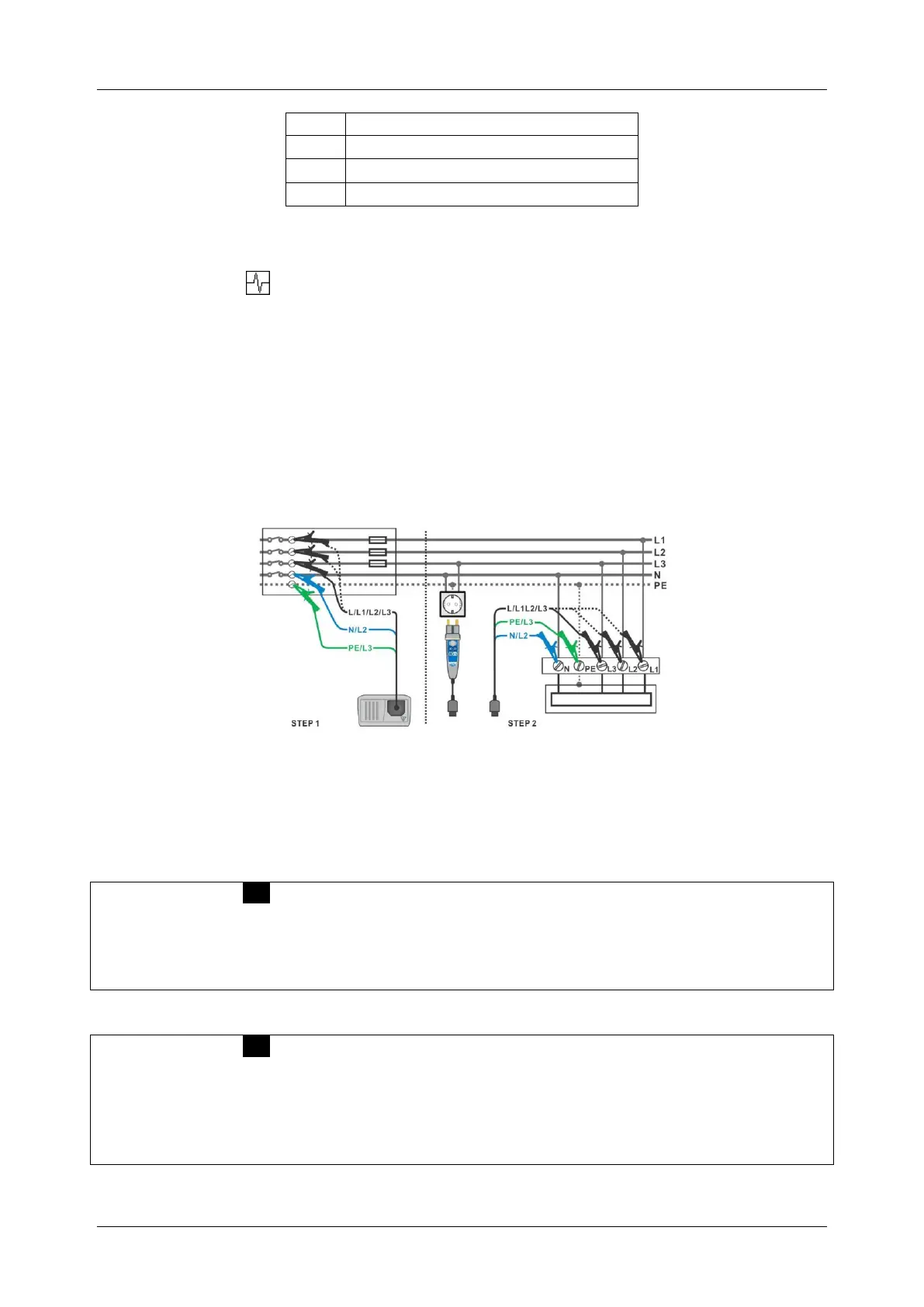
Circuits for measurement for voltage drop
Figure 5.30: Phase-neutral or phase-phase voltage drop measurement – connection of
plug commander and 3-wire test lead
Voltage drop measurement procedure
Step 1: Measuring the impedance Zref at origin
Select the ΔU sub-function using the function selector switch and / keys.
Select test parameters (optional).
Connect test cable to the instrument.
Connect the test leads to the origin of electrical installation (see figure 5.30).
Press the CAL key to perform the measurement.
Step 2: Measuring the voltage drop
Select the ΔU sub-function using the function selector switch and / keys.
Select test parameters (Fuse type must be selected).
Connect test cable or plug commander to the instrument.
Connect the test leads to the tested points (see figure 5.30).
Press the TEST key to perform the measurement.
Store the result by pressing the MEM key (optional)*.
* model MI 3125 BT

 Loading...