MI 3125 / BT EurotestCOMBO Measurements
49
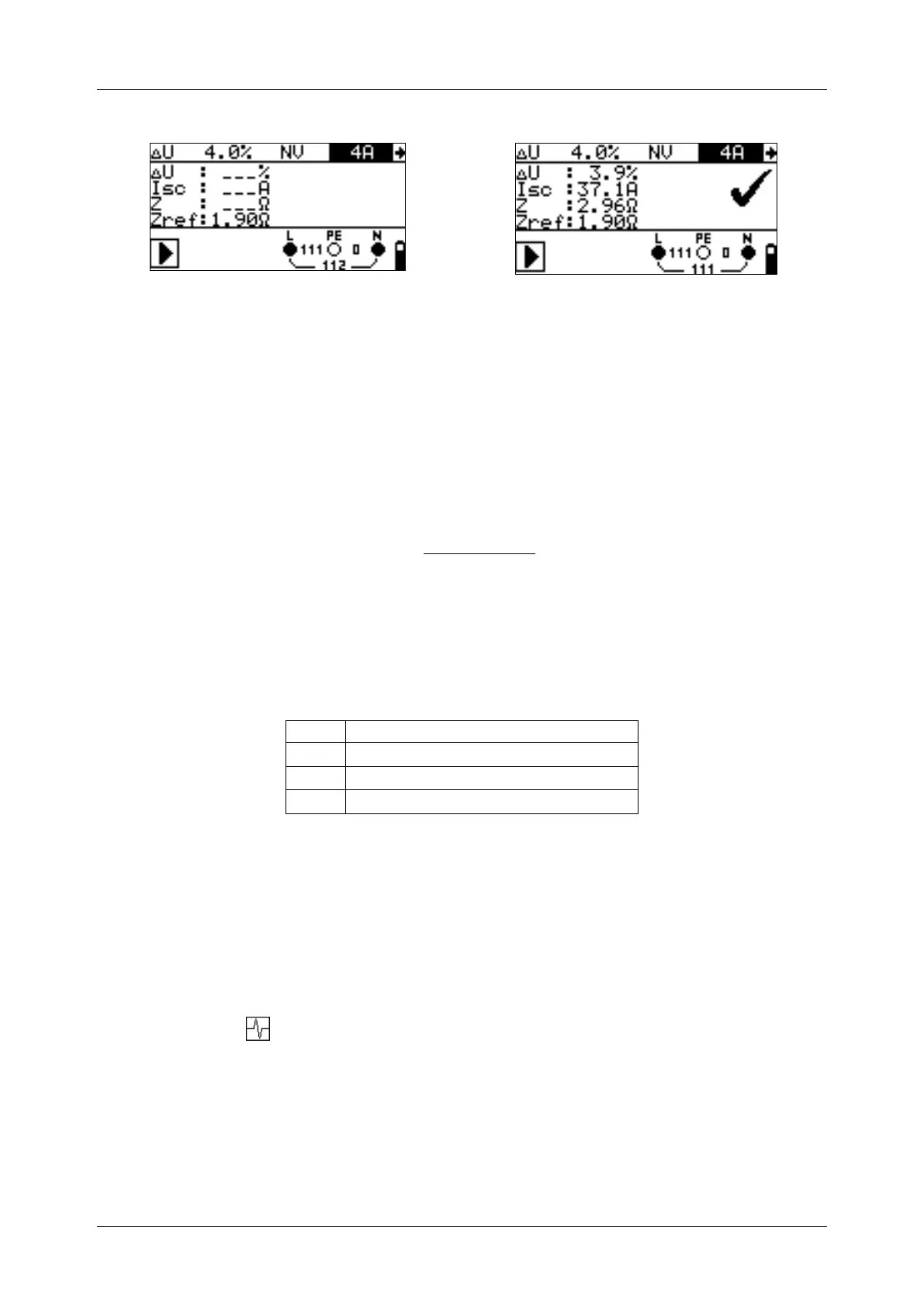
Figure 5.31: Examples of voltage drop measurement result
Displayed results:
ΔU ........... Voltage drop,
ISC ............ Prospective short-circuit current,
Z .............. Line impedance at measured point,
Zref .......... Reference impedance
Voltage drop is calculated as follows:
100
)(
%
N
NREF
U
IZZ
U
where:
ΔU ........ calculated voltage drop
Z………impedance at test point
Z
REF
…...impedance at reference point
I
N
………rated current of selected fuse
U
N
…….nominal voltage (see table below)
Input voltage range (L-N or L1-L2)
Note:
If the reference impedance is not set the value of Z
REF
is considered as 0.00 Ω.
The Z
REF
is cleared (set to 0.00 Ω) if pressing CAL key while instrument is not
connected to a voltage source.
I
SC
is calculated as described in chapter 5.6.1 Line impedance and prospective
short circuit current.
If the measured voltage is outside the ranges described in the table above the
ΔU result will not be calculated.
High fluctuations of mains voltage can influence the measurement results (the
noise sign is displayed in the message field). In this case it is recommended
to repeat few measurements to check if the readings are stable.
 Loading...