MI 3125 / BT EurotestCOMBO Measurements
47
Line impedance and prospective short circuit current
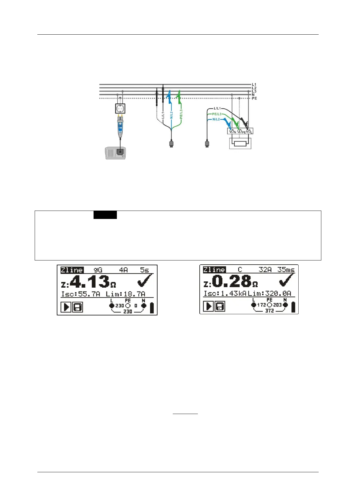
Circuits for measurement of line impedance
Figure 5.28: Phase-neutral or phase-phase line impedance measurement – connection
of plug commander and 3-wire test lead
Line impedance measurement procedure
* model MI 3125 BT
Select the Z-LINE sub-function.
Select test parameters (optional).
Connect test cable to the instrument.
Connect test leads to the item to be tested (see figure 5.28).
Press the TEST key to perform the measurement.
Store the result by pressing the MEM key (optional)*.
Figure 5.29: Examples of line impedance measurement result
Displayed results:
Z .............. Line impedance,
ISC ............ Prospective short-circuit current,
Lim .......... Low limit prospective short-circuit current value.
Prospective short circuit current is calculated as follows:
where:
Un ........ Nominal L-N or L1-L2 voltage (see table below),
ksc ....... Correction factor for Isc (see chapter 4.2.5).
 Loading...