MI 3125 / BT EurotestCOMBO Measurements
45
Fault loop impedance measurement procedure
* model MI 3125 BT
Select the Zloop or Zs rcd sub-function using the function selector switch and
/ keys
Select test parameters (optional).
Connect test cable to the Eurotest Combo.
Connect test leads to the item to be tested (see figure 5.24 and 5.17).
Press the TEST key to perform the measurement.
Store the result by pressing the MEM key (optional)*.
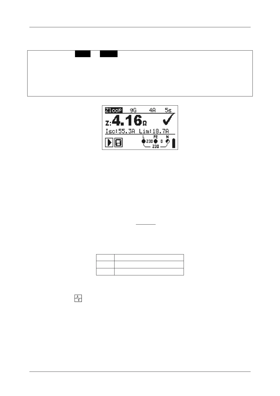
Figure 5.25: Examples of loop impedance measurement result
Displayed results:
Z .............. Fault loop impedance,
ISC ............ Prospective fault current,
Lim .......... Low limit prospective fault loop current value or high limit fault loop
impedance value for the UK version.
Prospective fault current I
SC
is calculated from measured impedance as follows:
where:
Un ........ Nominal U
L-PE
voltage (see table below),
ksc ....... Correction factor for Isc (see chapter 4.2.5).
Input voltage range (L-PE)
Notes:
High fluctuations of mains voltage can influence the measurement results (the
noise sign is displayed in the message field). In this case it is recommended
to repeat few measurements to check if the readings are stable.
This measurement will trip-out the RCD in RCD-protected electrical installation if
test Zloop is selected.
Select Zs rcd to prevent trip-out of RCD in RCD protected installation.

 Loading...