MI 3125 / BT EurotestCOMBO Measurements
30
Voltage measurement procedure
* model MI 3125 BT
Select the VOLTAGE TRMS function using the function selector switch.
Connect test cable to the instrument.
Connect test leads to the item to be tested (see figures 5.2 and 5.3).
Store voltage measurement result by pressing the MEM key (optional)*.
Measurement runs immediately after selection of VOLTAGE TRMS function.
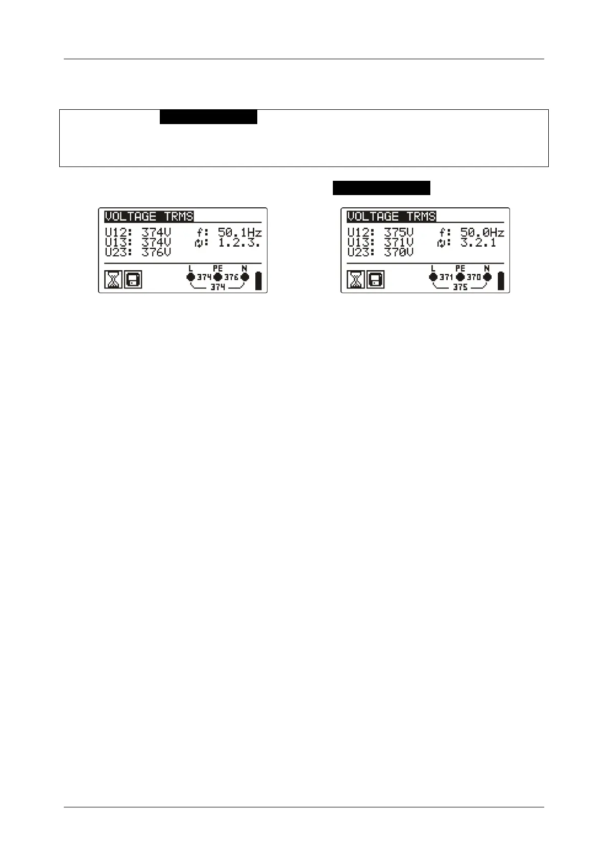
Figure 5.4: Examples of voltage measurement in three-phase system
Displayed results for single phase system:
Uln ........... Voltage between phase and neutral conductors,
Ulpe ......... Voltage between phase and protective conductors,
Unpe ........ Voltage between neutral and protective conductors,
f ............... frequency.
Displayed results for three-phase system:
U12 .......... Voltage between phases L1 and L2,
U13 .......... Voltage between phases L1 and L3,
U23 .......... Voltage between phases L2 and L3,
1.2.3 ........ Correct connection – CW rotation sequence,
3.2.1 ........ Invalid connection – CCW rotation sequence,
f ............... frequency.

 Loading...