MI 3125 EurotestCOMBO Testing RCD
32
5.5 Testing RCDs
Various test and measurements are required for verification of RCD(s) in RCD protected
installations. Measurements are based on the EN 61557-6 standard.
The following measurements and tests (sub-functions) can be performed:
Contact voltage,
Trip-out time,
Trip-out current,
RCD autotest.
See chapter 4.1 Function selection for instructions on
key functionality.
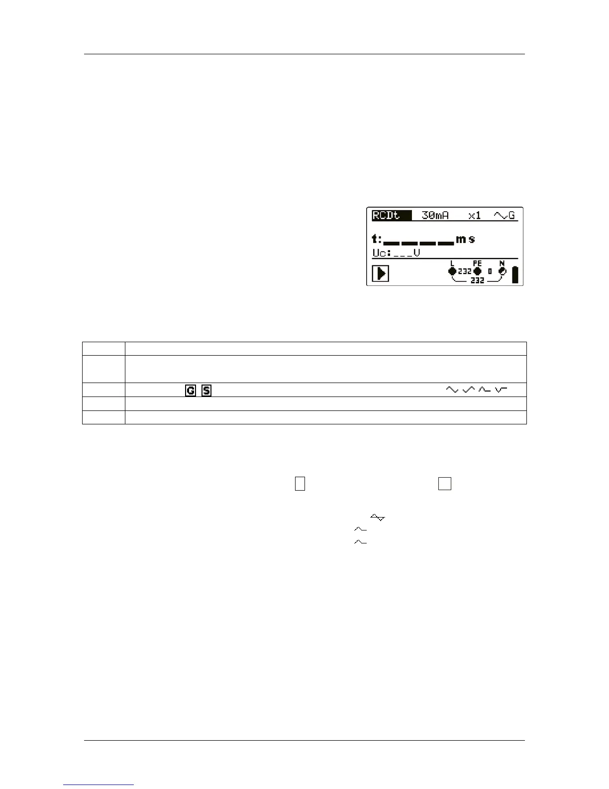
Figure 5.17: RCD test
Test parameters for RCD test and measurement
TEST RCD sub-function test [RCDt, RCD I, AUTO, Uc].
I
ΔN
Rated RCD residual current sensitivity I
ΔN
[10 mA, 30 mA, 100 mA, 300 mA,
500 mA, 1000 mA].
type
RCD type [ , ], test current waveform plus starting polarity [ , , , ].
MUL
Multiplication factor for test current [½, 1, 2, 5 I
ΔN
].
Ulim Conventional touch voltage limit [25 V, 50 V].
Notes:
Ulim can be selected in the Uc sub-function only.
The instrument is intended for testing of General (non-delayed) and
S
elective (time-
delayed) RCDs, which are suited for:
Alternating residual current (AC type, marked with symbol),
Pulsating residual current (A type, marked with symbol).
Pulsating residual current (A type, marked with symbol).
Time delayed RCDs have delayed response characteristics. As the contact voltage pre-
test or other RCD tests influence the time delayed RCD it takes a certain period to
recover into normal state. Therefore a time delay of 30 s is inserted before performing
trip-out test by default.

 Loading...