MI 3125 InstaltestCOMBO Connector panel
13
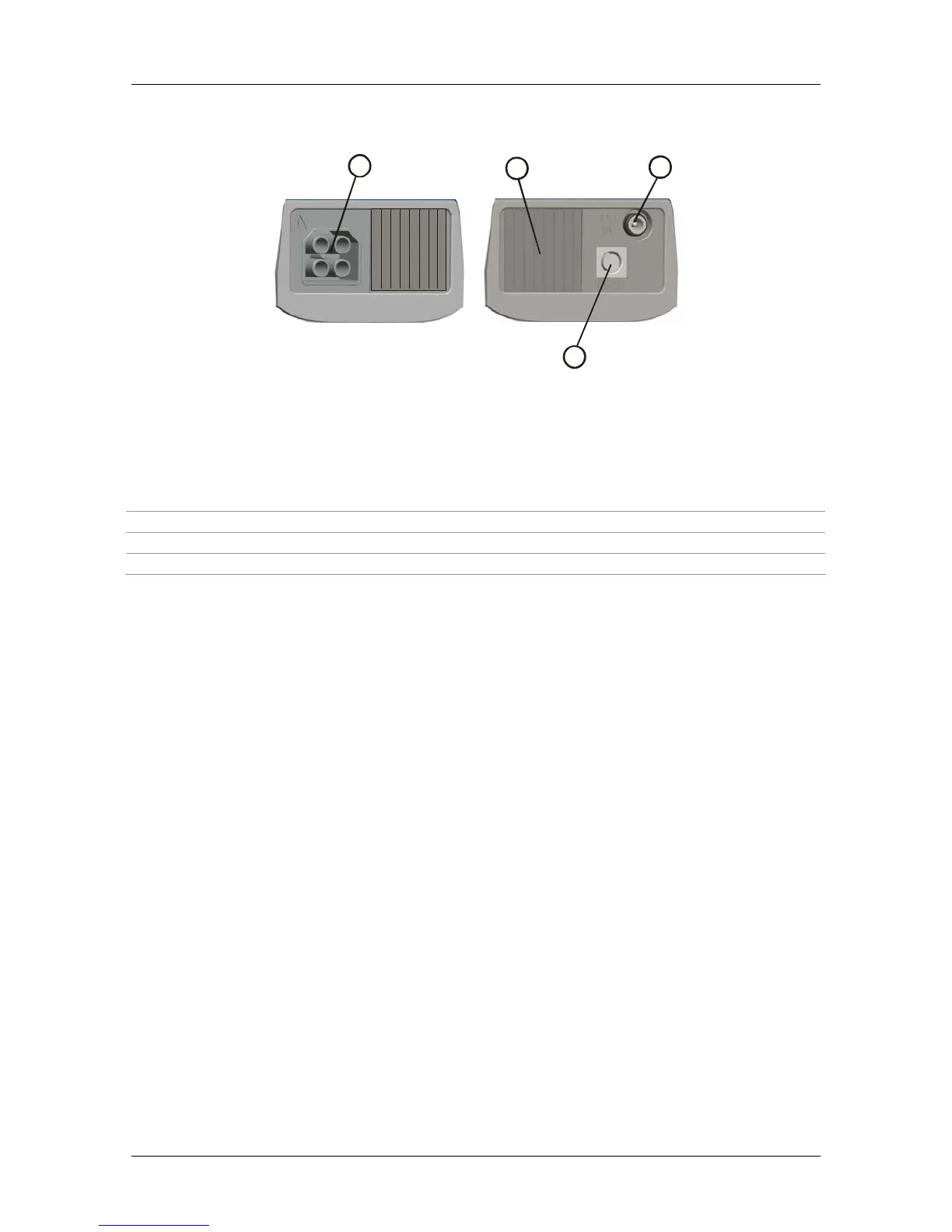
3.2 Connector panel
1
23
4
Figure 3.2: Connector panel
Legend:
1 Test connector Measuring inputs / outputs
2 Protection cover
3 Charger socket
4 PS/2 connector Serial port for upgrading the instrument.
Warnings!
Maximum allowed voltage between any test terminal and ground is 600 V!
Maximum allowed voltage between test terminals is 600 V!
Maximum short-term voltage of external power supply adapter is 14 V!

 Loading...