EasyManua.ls Logo

Metro DataVac C5 E-Series - User Manual

Metro DataVac C5 E-Series
12 pages
Print Icon
To Next Page IconTo Next Page
Loading...
INSTRUCTIONS FOR USE
C5 E-SERIES
HEATED HOLDING & PROOFING CABINETS
DESCRIPTION
This manual covers cabinets with electrical ratings of: 120V, 60 Hz, 2000W and
220-240V, 50/60 Hz, 1681-2000W
© 2018 InterMetro Industries Corporation, Wilkes-Barre, PA 18705
L01-633 01/2019
Metro Heated Cabinets are for
Hot Food Holding applications only.
TABLE OF CONTENTS
Safety Information & Symbols ...................................... 2
Identifying your Cabinet................................................2
Installation and Setup ...................................................3
Operating Instructions ..................................................4
Care and Maintenance .................................................4
Basic Troubleshooting ..................................................5
Reversing the Door ....................................................... 6
Service and Replacement Parts ................................... 7
Service and Replacement Parts (Circuits) ................... 9
Warranty ......................................................................10
Question and Answer IconNeed help?

Do you have a question about the Metro DataVac C5 E-Series and is the answer not in the manual?

Overview

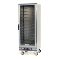
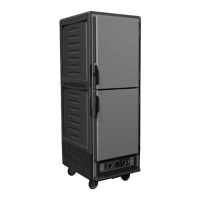
The Metro C5 E-Series Heated Holding & Proofing Cabinets are designed for hot food holding applications. These cabinets are not re-thermalizing units; food must be at the appropriate temperature before being placed inside. Users should always pre-heat the cabinet to the desired temperature and use a food probe to check internal food temperature, as the cabinet temperature does not necessarily reflect the internal food temperature.

Technical Specifications:

The manual covers cabinets with the following electrical ratings:

  • 120V, 60 Hz, 2000W (Model: C5E9-CFC-U)
  • 220-240V, 50/60 Hz, 1681-2000W (Model: C5E9-CXFC-U)

For 120V units, the amp draw is approximately 16 amps in HOLD mode and 6.0 amps in PROOF mode. For 220-240V models, the amp draw is approximately 8 amps in HOLD mode and 3.0 amps in PROOF mode.

Installation and Setup:

  1. Inspection: Upon receipt, check both the packaging and the cabinet for any shipping damage. Any visible damage must be reported to the freight company within 48 hours and noted on the freight bill. Concealed damage must be reported within 15 days. Retain original packaging if damage is found.
  2. Protective Covers: Remove any plastic or paper protective covers before operating the cabinet.
  3. Water Pans: Ensure the stainless steel water pan is installed inside the cabinet, in the floor opening on top of the proofing element. The plastic drip pan should be installed underneath the drip trough at the base of the cabinet. It is crucial that the stainless steel water pan and plastic drip pan are not used together inside the cabinet during operation.
  4. Universal Slides: Install the universal slides into the notches built into the cabinet walls. These notches are spaced at 1.5-inch intervals. Each cabinet comes with 12 sets of slides; additional sets can be ordered using part number C5-USLIDEPR-C.
  5. Electrical Connection: With the POWER switch OFF, plug the cord into the appropriate rated, grounded receptacle.
    • 120V cabinets require a 20 amp 125 VAC receptacle.
    • 220-240V cabinets require a 15 amp 250 V receptacle.
    • Do not store or accumulate combustible materials on, under, or next to the cabinet, and do not block any ventilation louvers or slots.

Operating Instructions:

The cabinet features a control panel with a Power/Selector Switch, Thermostat, and Thermometer.

  1. Humidity: To achieve adequate humidity in proofing or heated holding mode, fill the stainless steel pan with water.
  2. Power/Selector Switch: This is a 3-way switch:
    • "Hold" (up): For heated holding.
    • "Proof" (down): For proofing.
    • "Off" (middle): To power down the unit.
  3. Heated Holding Mode:
    • Set the selector switch to "hold."
    • The thermostat, set at desired setting in red holding range (number 7), corresponds to approximately 150°F (66°C), with 10 being approximately 190°F (88°C).
    • Monitor temperature read-out on the thermometer and adjust the thermostat to fine-tune the temperature as necessary.
  4. Proofing Mode:
    • Set the selector switch to "proof."
    • The thermostat, set at desired setting in blue proofing range, provides approximate temperature yields. These yields vary based on a pre-determined humidity level:
      • Number 1: approximately 85°F (30°C)
      • Number 2: approximately 95°F (35°C)
      • Number 3: approximately 105°F (41°C)
    • Monitor temperature read-out on the thermometer and adjust the thermostat to fine-tune the temperature as necessary.
    • When the switch is set to hold or proof, the fan is always energized. To power off the fan and the unit, set the switch to "off" (middle).

Maintenance Features:

  • Cleaning:
    • Unplug the cabinet before cleaning or servicing.
    • Do not wash the cabinet with a water jet or high-pressure water.
    • Do not spray or pour water into the module.
    • Wipe the cabinet with a damp cloth and dry with a towel.
    • Use only cleaning agents approved for aluminum.
    • Do not use cleaners with chlorides or phosphates, as they may cause damage to stainless steel and aluminum.
    • Ensure the cabinet has cooled down before cleaning. Use cleaners in proper concentrations. Follow the manufacturer's directions for the cleaning product used.
    • Use a damp cloth or sponge with mild soap suitable for aluminum. Dry with a clean towel. Wipe up spills as soon as possible and regularly clean the cabinet to avoid staining and difficult to clean conditions.
  • Caster Maintenance: Regularly inspect the casters. Keeping them free of dirt build-up will prolong their life.
  • Fasteners: Periodically tighten loose fasteners and replace worn or damaged parts with new InterMetro approved parts. This includes door latch and hinge screws.

Troubleshooting:

  • Controls Not Working (No Heat/Fan):
    • Check if the cabinet is plugged in and if the outlet has power.
    • Ensure the power switch is in the "On" position.
    • Verify cabinet wiring from the power cord to the power switch and thermostat.
    • Confirm the correct mode (HOLD for holding, PROOF for proofing).
  • Temperature Too Hot:
    • Initial pre-heat may overshoot the set point.
    • If the displayed temperature exceeds 220°F (104°C):
      • Blower wiring may be faulty or disconnected, requiring blower replacement.
      • The thermostat may have failed, and the thermal cut-out device is controlling the temperature.
      • The thermal cut-out device itself may have failed.
  • Temperature Too Low:
    • The cabinet may still be in pre-heat or recovering from the door being opened.
    • Check if the door is closed and sealing properly. Replace worn-out door gaskets.
    • If the blower is not circulating air, its wiring may be faulty or disconnected.
  • No Heat Generated:
    • Check if the air heater element is faulty.
    • Verify the wiring to the air heater element for faults or disconnections.
    • The thermostat may be faulty.
    • The thermal cut-out may be open or have a disconnected wire.

Reversing the Door:

The door can be reversed for right- or left-hand opening. The cabinet is shipped with hinges on the right.

  1. With the door closed, remove the hinge pin by driving it out with a hammer and a small diameter screwdriver.
  2. Grasp the door firmly, pull the latch lever to release it, and set it aside carefully to avoid damaging the gasket.
  3. Remove screws from the left side of the cabinet. Remove the cabinet-mounted part of the hinge and remount it to the left side. Place the screws removed from the left side into the remaining holes on the right side. Tighten all screws.
  4. Relocate the latch plate(s) from the left side to the right by removing the two mounting screws. Tighten all screws.
  5. Rotate the door 180 degrees. Align the door-mounted hinge part with the cabinet-mounted hinge part and tap the hinge pin into place until the top of the pin is flush with the top of the cabinet-mounted hinge part. Invert the door latch by removing the black plastic screw covers and the screws holding the latch in place.

Warranty:

InterMetro Industries Corporation warrants products to be free from defects in workmanship and material for one year from the date of shipment. This warranty is exclusive and in lieu of all other warranties. If a product is defective and has not been altered, InterMetro will, at its option, repair or replace the part. Labor charges apply after one year. Products cannot be returned without prior written approval. Seller's liability is limited to the cost of correcting defective parts. To ensure warranty implementation, return the completed registration card within 15 days of receipt to InterMetro Industries Corp., Wilkes-Barre, PA 18705. Online registration is also available at www.metro.com/service-support/thermal-cabinets.

Metro DataVac C5 E-Series Specifications

General IconGeneral
BrandMetro DataVac
ModelC5 E-Series
CategoryHeater
LanguageEnglish

Related product manuals