4.1 Setting the wavelength
■■■■■■■■■■■■■■■■■■■■■■
10
■■■■■■■■
Optrode
4 Operation and maintenance
4.1 Setting the wavelength
The Optrode has eight LEDs (LED = light-emitting diode) on its optical cir-
cuit board that serve as light sources. Each LED emits light in a different
wavelength range. The LEDs are labeled with their primary wavelength on
the optical circuit board. It is easy to recognize which LED is active and
which wavelength is set by the fact that the label is lit in the correspond-
ing color.
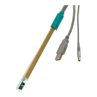
Figure 9
Wavelength display of the Optrode
Table 1 Wavelength ranges
LED Color Usable wavelength range / nm
470 blue 460 - 480
502 blue-green 485 - 520
520 green 505 - 535
574 yellow-green 560 - 585
590 yellow-orange 575 - 605
610 orange 595 - 625
640 light red 620 - 655
660 red 650 - 670
The magnetic switch in the sensor head is used to switch between LEDs or
it is done automatically via tiamo (version 2.5 and higher).
Switching between LEDs with magnet
The wavelength is changed manually as follows:
1
Hold a magnet, e.g. a stirring bar, against the magnet symbol.